

You Can Build A Giant 7-Segment Display Of Your Very Own
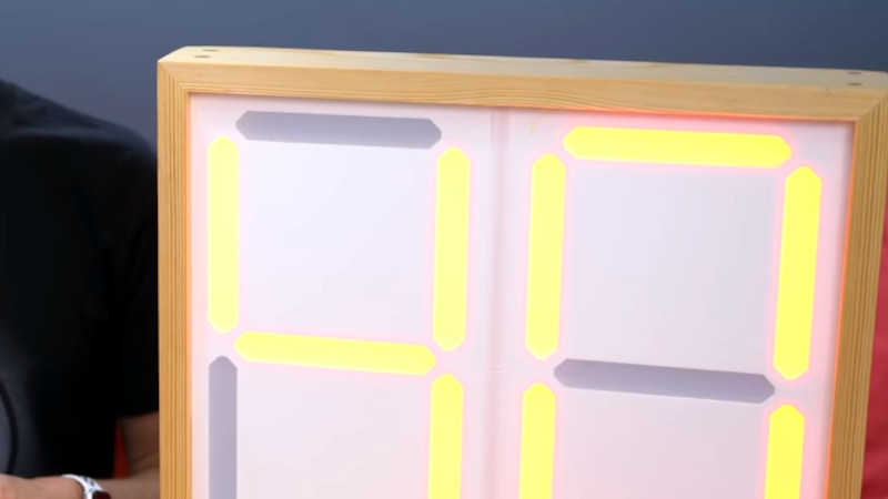
Sometimes you need to display a number nice and large, making it easily readable at a good distance. [Lewis] has just the thing for that: a big expandable 7-segment display.
The build is modular, allowing it to be extended from 2 to 10 digits and beyond. The digits themselves are made of 3D-printed parts assembled onto acrylic. These can then be ganged up in a wooden frame for displaying larger numbers with more digits. Individual elements are lit by addressable LEDs, and the project can be built using an Arduino Nano or an ESP8266 for control. The latter opens up possibilities for controlling the screen over WiFi, which could prove useful.
[Lewis] has built his own version for a local swim club, where it will be used as a laptimer. Other applications could be as a scoreboard in various sports, or to confuse your neighbours by displaying random numbers in your front yard.
We’ve seen a similar build from [Ivan Miranda] that served well as a workshop clock , too. Video after the break.

7 thoughts on “ You Can Build A Giant 7-Segment Display Of Your Very Own ”
I see a back-ground and I want to paint it bla-aack (with apologies to the Stones)
The Animals performed the song at the Monterey Pop Festival.
I agree. The white background seems to make for a low contrast to the illuminated segments, with the unlit ones too contrasty. Yet the unlit segments on the displays shown in the corny examples are lower contrast, presumably just made-up graphics rather than photos of the actual completed displays?
I used dark gray for Sizable7 ( https://sizable7.nickstick.nl ). Experimented with several colors and materials. The one I choose gave the best contrast I think.
Or to Vanessa Carlton, who does brilliant cover! (better than the original IMVHO 😁)
Black or dark grey.
I got into an argument with my senior years ago on a church organ installation where the speakers had to be covered in white grill cloth, the whole place was white. He painted the wood face of the speakers white in the shop and then at the church he put the cloth on and black circles show up through the pristine whiteness. Guess what he did next. It involved white paint. You can’t paint a shadow! Circles still showed up.
When I found out, ooh. I told him if it’s all dark besides the cones are set back, there is minimal contrast. I had to show him. Paint it black and when covered in white scrim it looks white enough and has no pattern showing through. Same principal here.
Get diffusing plastic from any cracked flat panel TV, or use the whole TV gutted and make a big clock etc. Portable with the low stand they have.
This is a great help. My plans are to have a sign on our residential street where many race up to 2 x the 25 mph speed limit to show the cars their speed.
Leave a Reply Cancel reply
Please be kind and respectful to help make the comments section excellent. ( Comment Policy )
This site uses Akismet to reduce spam. Learn how your comment data is processed .
Never miss a hack
If you missed it.

Mining And Refining: Fracking

Programming Ada: Records And Containers For Organized Code

A Treasure Trove In An English Field

How Facebook Killed Online Chat

The Tragic Story Of The Ill-Fated Supergun
Our columns.

FLOSS Weekly Episode 786: What Easy Install Script?
Displays We Like Hacking: HDMI

Pasteurisation: Probably Why You Survived Childhood

Tech In Plain Sight: Theodolites

Hackaday Links: June 2, 2024
By using our website and services, you expressly agree to the placement of our performance, functionality and advertising cookies. Learn more

- Raspberry Pi
- DIY Electronics
- Programming
Select Page
How to Set up Seven Segment Displays on the Arduino
Posted by Krishna Pattabiraman | Arduino | 44
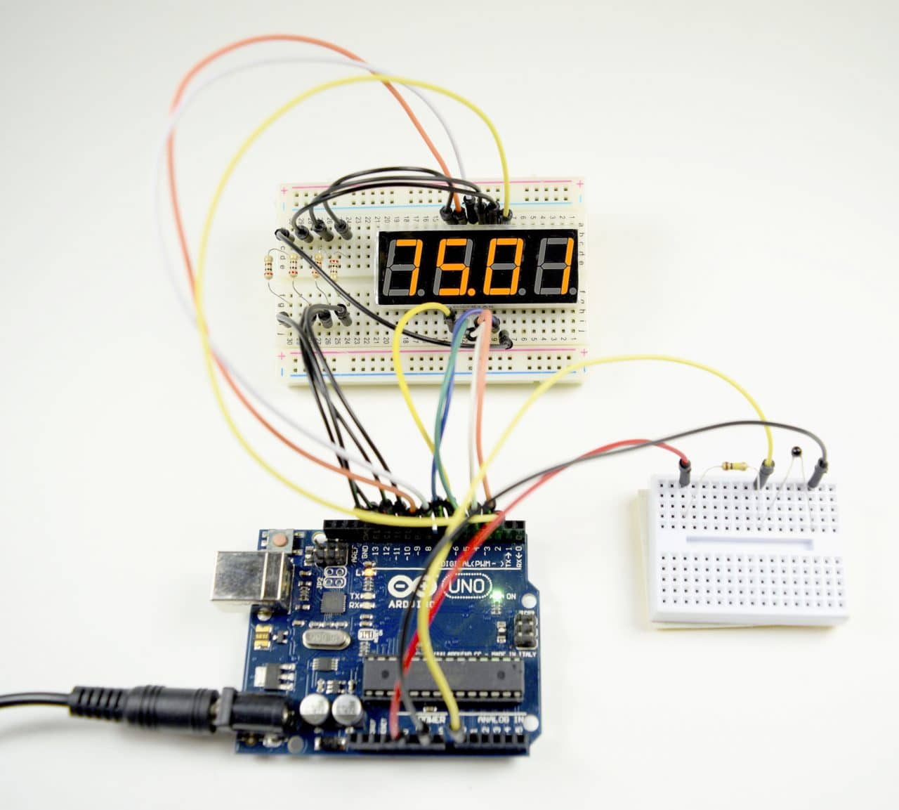
Seven segment displays are used in common household appliances like microwave ovens, washing machines, and air conditioners. They’re a simple and effective way to display numerical information like sensor readings, time, or quantities. In this tutorial, we’ll see how to set up and program single digit and multi-digit seven segment displays on an Arduino .

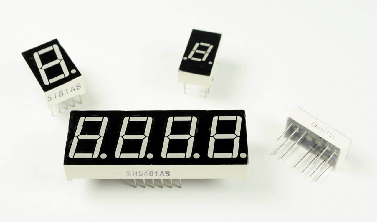
Seven segment displays come in a wide variety of sizes and colors. Red , blue , and green are the easiest colors to find. Sizes range from small 0.56 inch displays up to large 4 inch and even 6.5 inch displays . Some displays have a single digit , and others have two or four .
Before we start working with 7 segment displays, we need to understand some of the basics of LEDs and how to control them.
Watch the video for this tutorial here:
A single LED consists of two terminals, an anode and a cathode. The anode is the positive terminal and the cathode is the negative terminal:
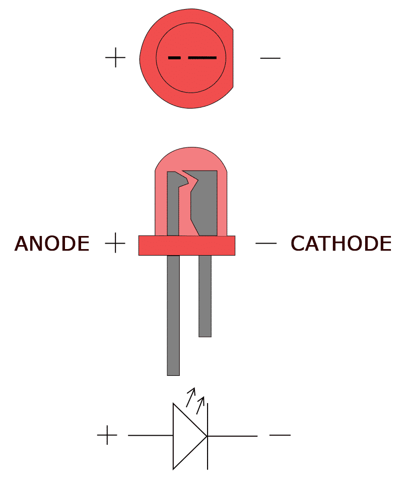
To power the LED, you connect the cathode to ground and the anode to the voltage supply. The LED can be turned on or off by switching power at the anode or the cathode.
Anode to GPIO
With the LED’s anode connected to a digital pin, the cathode is connected to ground:
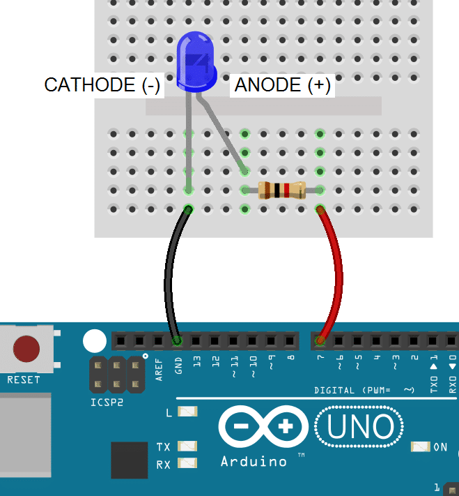
Note: All LEDs need a current limiting resistor placed on either the anode side or cathode side to prevent the LED from burning out. The resistor value will determine how bright the LED shines. 1K ohms is a good place to start, but you can calculate the ideal value with an LED resistor calculator .
To light up an LED with the anode connected to a digital pin, you set the digital pin to HIGH:
In the void setup() block, we configure GPIO pin 7 as an output with pinMode(7, OUTPUT) and drive it high with digitalWrite(7, HIGH) .
Cathode to GPIO
With an LED’s cathode connected to a digital pin, the anode is connected to Vcc. To turn on the LED, the digital pin is switched LOW, which completes the circuit to ground:
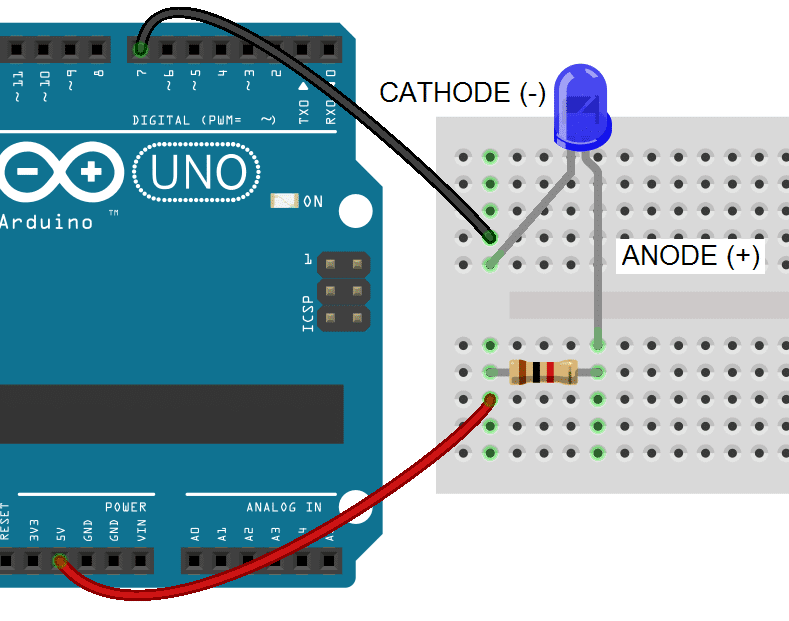
In this case we drive GPIO pin 7 LOW with digitalWrite(7, LOW) . This closes the circuit and allows current to flow from Vcc to ground:
How 7-Segment Displays Work
Seven segment displays consist of 7 LEDs, called segments, arranged in the shape of an “8”. Most 7-segment displays actually have 8 segments, with a dot on the right side of the digit that serves as a decimal point. Each segment is named with a letter A to G, and DP for the decimal point:
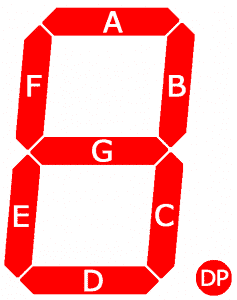
Each segment on the display can be controlled individually, just like a regular LED.
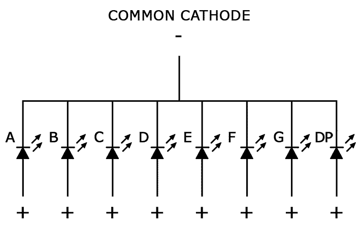
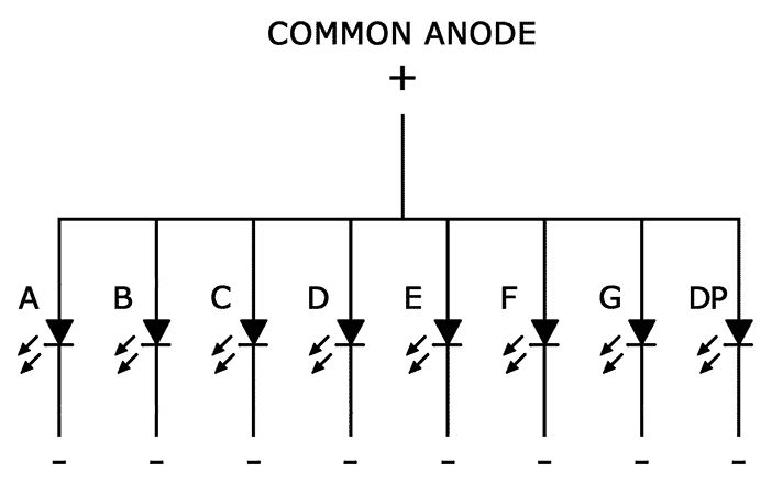
There are two types of 7-segment displays – common cathode and common anode .
Common Cathode Displays
In common cathode displays, all of the cathodes are connected to ground and individual segments are turned on and off by switching power to the anodes:
Common Anode Displays
In common anode displays, all of the anodes are connected to Vcc, and individual segments are turned on and off by switching power to the cathodes:
Connecting 7-Segment Displays to the Arduino
Single digit seven segment displays typically have 10 pins. Two pins connect to ground, and the other 8 connect to each of the segments. Here is a pin diagram of the popular 5161AS common cathode display :
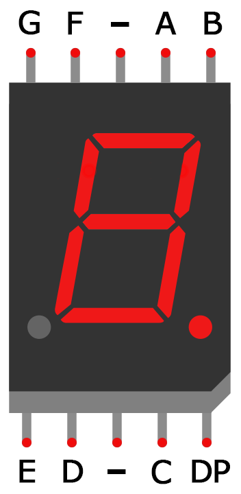
Before you can connect your display to the Arduino, you need to know if it’s common anode or common cathode, and which pins connect to each segment. This information should be in the datasheet, but if you can’t find the datasheet or you don’t know your display’s part number, I’ll show you how to figure this out below…
How to Tell If You Have a Common Anode or Common Cathode Display
To determine if a display is common anode or common cathode, you can probe the pins with a test circuit constructed like this:
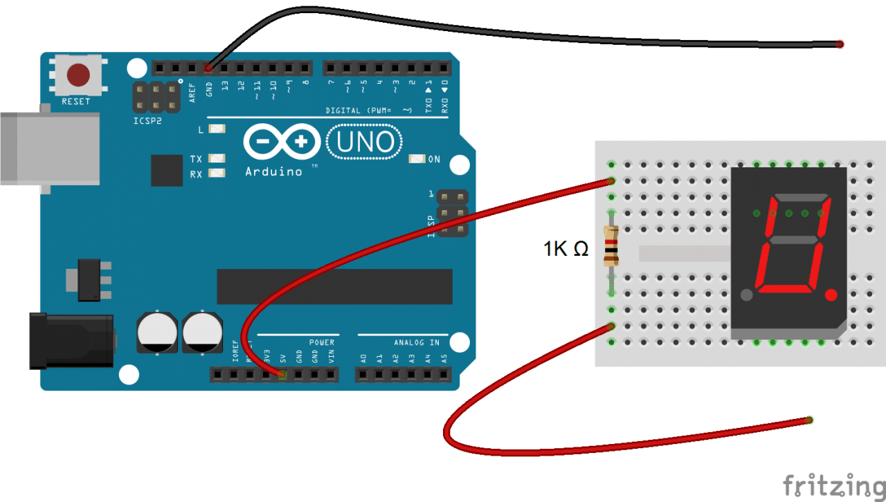
Connect the ground (black) wire to any pin of the display. Then insert the positive (red) wire into each one of the other pins. If no segments light up, move the ground wire over to another pin and repeat the process. Do this until at least one segment lights up.
When the first segment lights up, leave the ground wire where it is, and connect the positive wire to each one of the other pins again. If a different segment lights up with each different pin, you have a common cathode display. The pin that’s connected to the ground wire is one of the common pins. There should be two of these.
If two different pins light up the same segment, you have a common anode display. The pin that’s connected to the positive wire is one of the common pins. Now if you connect the ground wire to each one of the other pins, you should see that a different segment lights up with each different pin.
How to Determine the Pinout for Your Display
Now draw a diagram showing the pins on your display. With the common pin connected to the ground wire (common cathode) or positive wire (common anode), probe each pin with the other wire. When a segment lights up, write down the segment name (A-G, or DP) next to the corresponding pin on your diagram.
Connecting Single Digit Displays to the Arduino
Once you have the pin layout figured out, connecting the display to an Arduino is pretty easy. This diagram shows how to connect a single digit 5161AS display (notice the 1K ohm current limiting resistor connected in series with the common pins):
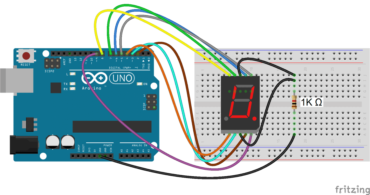
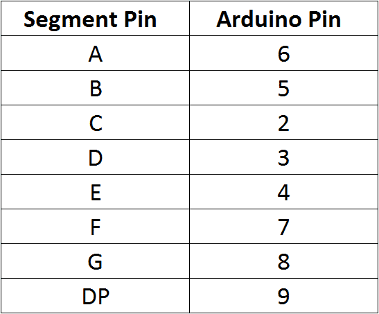
In the example programs below, the segment pins connect to the Arduino according to this table:
Programming Single Digit Displays
Install the library.
We’ll use a library called SevSeg to control the display. The SevSeg library works with single digit and multi-digit seven segment displays. You can download the library’s ZIP file from GitHub or download it here:
To install it, open the Arduino IDE, go to Sketch > Include Library > Add .ZIP Library, then select the SevSeg ZIP file that you downloaded.
Printing Numbers to the Display
This program will print the number “4” to a single digit 7-segment display:
In this program, we create a sevseg object on line 2. To use additional displays, you can create another object and call the relevant functions for that object. The display is initialized with the sevseg.begin() function on line 11. The other functions are explained below:
hardwareConfig = COMMON_CATHODE – This sets the type of display. I’m using a common cathode, but if you’re using a common anode then use COMMON_ANODE instead.
byte numDigits = 1 – This sets the number of digits on your display. I’m using a single digit display, so I set it to 1. If you’re using a 4 digit display, set this to 4.
byte digitPins[] = {} – Creates an array that defines the ground pins when using a 4 digit or multi-digit display. Leave it empty if you have a single digit display. For example, if you have a 4 digit display and want to use Arduino pins 10, 11, 12, and 13 as the digit ground pins, you would use this: byte digitPins[] = {10, 11, 12, 13} . See the 4 digit display example below for more info.
byte segmentPins[] = {6, 5, 2, 3, 4, 7, 8, 9} – This declares an array that defines which Arduino pins are connected to each segment of the display. The order is alphabetical (A, B, C, D, E, F, G, DP where DP is the decimal point). So in this case, Arduino pin 6 connects to segment A, pin 5 connects to segment B, pin 2 connects to segment C, and so on.
resistorsOnSegments = true – This needs to be set to true if your current limiting resistors are in series with the segment pins. If the resistors are in series with the digit pins, set this to false. Set this to true when using multi-digit displays.
sevseg.setBrightness(90) – This function sets the brightness of the display. It can be adjusted from 0 to 100.
sevseg.setNumber() – This function prints the number to the display. For example, sevseg.setNumber(4) will print the number “4” to the display. You can also print numbers with decimal points. For example, to print the number “4.999”, you would use sevseg.setNumber(4999, 3) . The second parameter (the 3) defines where the decimal point is located. In this case it’s 3 digits from the right most digit. On a single digit display, setting the second parameter to “0” turns on the decimal point, while setting it to “1” turns it off.
sevseg.refreshDisplay() – This function is required at the end of the loop section to continue displaying the number.
Count Up Timer
This simple program will count up from zero to 9 and then loop back to the start:
The code is similar to the previous sketch. The only difference is that we create a count variable “i” in the for statement on line 16 and increment it one number at a time.
The sevseg.setNumber(i, i%2) function prints the value of i. The i%2 argument divides i by 2 and returns the remainder, which causes the decimal point to turn on every other number.
The count up timer is a nice way to demonstrate the basics of how to program the display, but now let’s try to make something more interesting.
Rolling Dice
This example consists of a push button and a single 7 segment display. Every time the push button is pressed and held, the display loops through numbers 0-9 rapidly. Once the button is released, the display continues to loop for a period of time almost equal to the time the button was pressed, and then displays a number along with the decimal point to indicate the new number.
To build the circuit (with the 5161AS display), connect it like this:
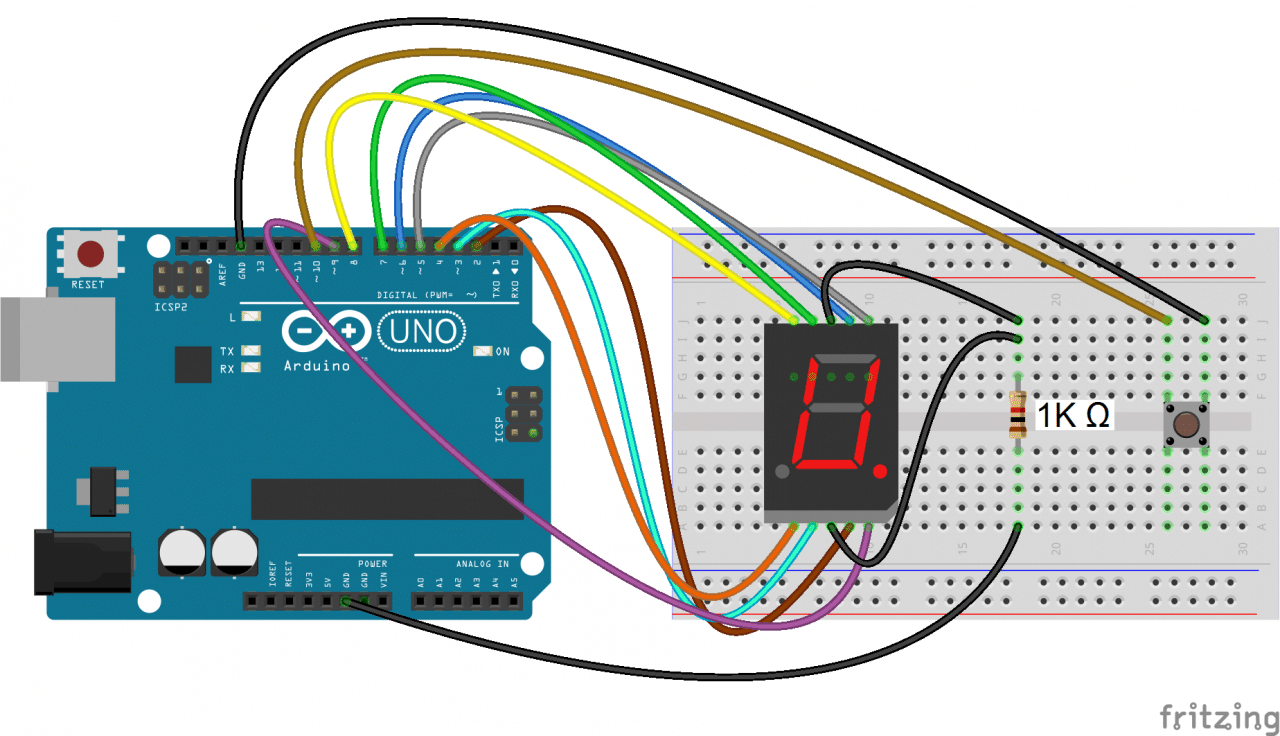
Then upload this program to the Arduino:
4 Digit 7-Segment Displays
So far we have only worked with single digit 7-segment displays. To display information such as the time or temperature, you will want to use a 2 or 4 digit display, or connect multiple single digit displays side by side.
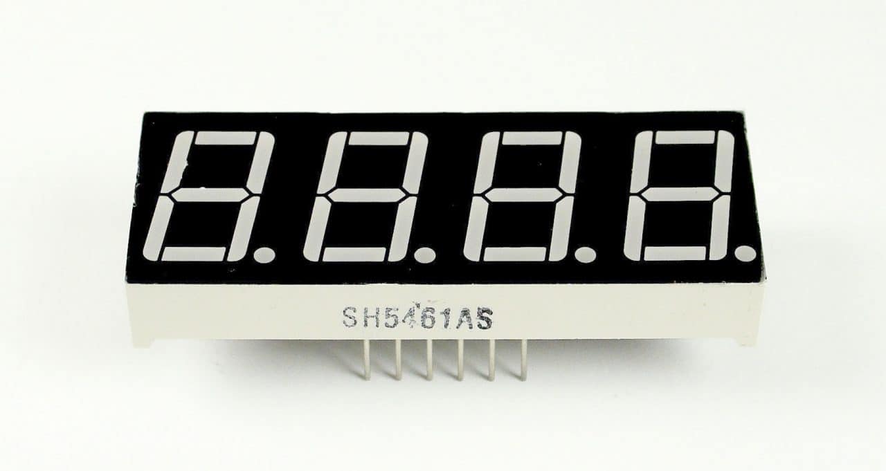
In multi-digit displays, one segment pin (A, B, C, D, E, F, G, and DP) controls the same segment on all of the digits. Multi-digit displays also have separate common pins for each digit – these are the digit pins. You can turn a digit on or off by switching the digit pin.
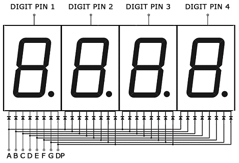
I’m using a 4 digit 7-segment display with the model number 5641AH , but the wiring diagrams below will also work with the 5461AS.
Here is a diagram showing the pinout of these displays:
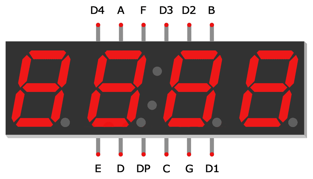
The digit pins D1, D2, D3 and D4 need to be connected to current limiting resistors, since they are the common terminals of the digits. The connections are shown below:
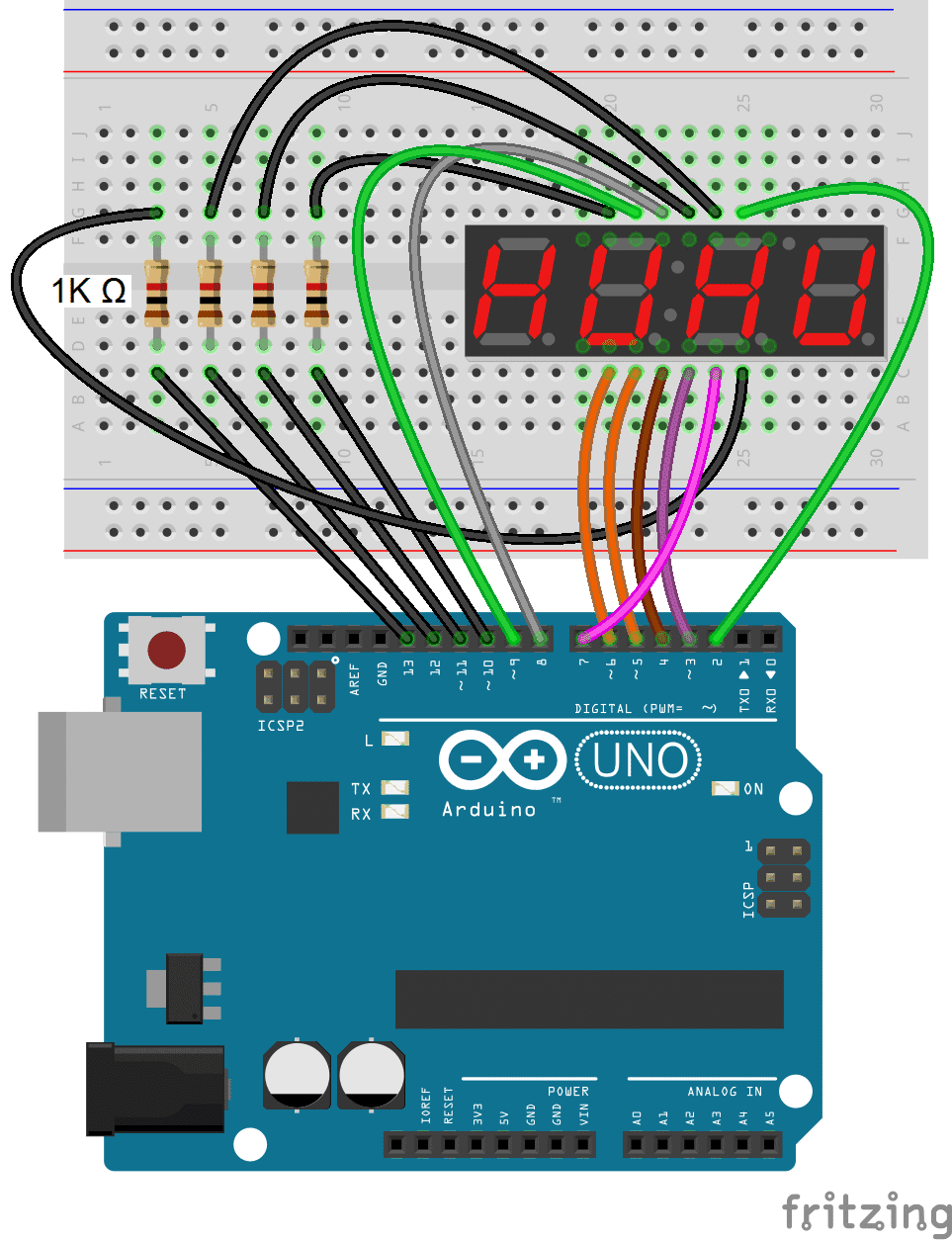
This simple program will print the number “4.999” to the display:
In the code above, we set the number of digits in line 5 with byte numDigits = 4 .
Since multi-digit displays use digit pins, we also need to define which Arduino pins will connect to the digit pins. Using byte digitPins[] = {10, 11, 12, 13} on line 6 sets Arduino pin 10 as the first digit pin, Arduino pin 11 to the second digit pin, and so on.
To print numbers with a decimal point, we set the second parameter in sevseg.setNumber(4999, 3) to three, which puts it three decimal places from the right most digit.
Displaying Sensor Data
Now let’s read the temperature from a thermistor and display it on a 4 digit display.
Connect the circuit like this:
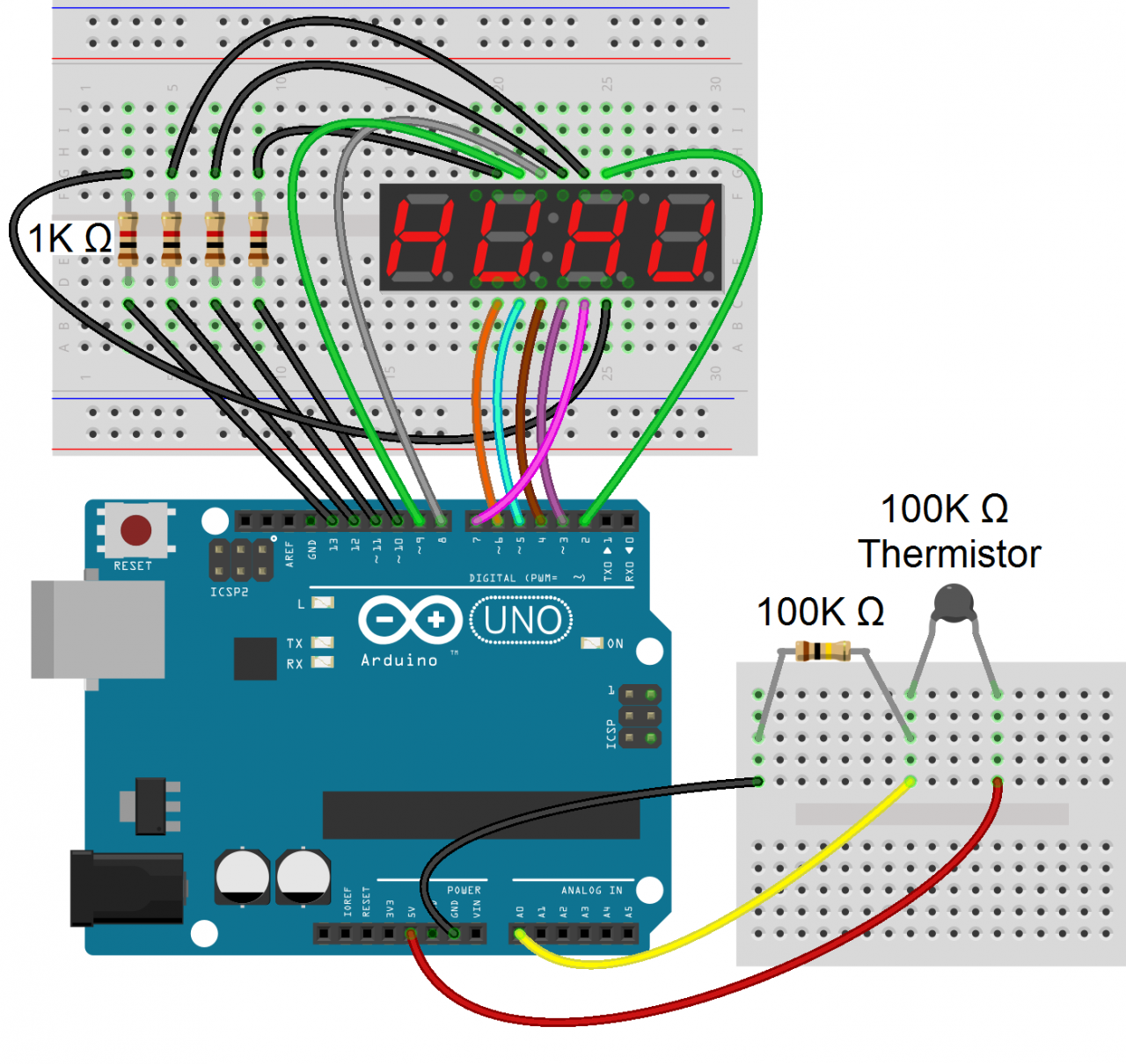
If you want to learn more about thermistors, check out our tutorial on using a thermistor with an Arduino .
Once everything is connected, upload this code to the Arduino:
This will display the temperature in Fahrenheit on the 7-segment display. To display the temperature in Celsius, comment out line 28.
By itself, the display will update every time the temperature changes even slightly. This creates an annoying flickering. In order to deal with this, we introduce a timer mechanism, where we only read the value from the thermistor every 300 milliseconds (lines 30 to 34).
The temperature variable “T” is printed to the display on line 35 with sevseg.setNumber(T, 2, false) .
Hopefully this article should be enough to get you started using seven segment displays. If you want to display readings from other sensors, the example program above can easily be modified to do that. If you have any questions or trouble setting up these circuits, feel free to leave a comment below.

Related Posts

How to Set Up the BMP180 Barometric Pressure Sensor on an Arduino
May 29, 2017
How to Setup a GPS Sensor on the Arduino
September 30, 2021
How to Setup Gyroscopes on the Arduino
October 19, 2021
How to Setup Vibration Sensors on the Arduino
October 5, 2021
44 Comments
Thanks for these tutorials about using the NTC probe with the Arduino. What I would also like is using setpoint buttons to control a relais. Many thanks.
Learn how to build this without Arduino for just £3. Search “odonodesign temperature” on google to find out how.
Thank you so much! FINALLY got it working, now I can tinker all I want :) This is by far the clearest explanation out there.
kid wow https://t.co/DiuUrfMbzF
Lovely tutorial got it to work easily. I have 1 problem which is that I need to let the display count down with all 4 numbers displayed at once. Right now with the count up code above because of the `delay(1000);` it displays 1 number at a time. It starts with the first number on the display then goes on to the next until it went through all 4 and it will go back to the first. Is there a way around it to display all 4 digits at once while still counting down in seconds?
i have this same problem
Shouldn’t you use 8 resistors, one on each segment channel instead of the ground? Like this , a single segment used will burn brighter than all 8 segments used. When you put a resistor on each segment the resistance goes up a fraction for every segment used.
Hi ,good project ,what is with negative temperature ?How can put “–” mark?
One resistor is enough. The led on each segment are not in the same state (ON/OFF)per time no matter what you wrote. The led change state at a very fast speed not visible to the eye(Persistent of Vision,POV). This has been taking care off in the library downloaded.
No, the original poster is correct. The current of all the LEDS is shared by the single resistor, so the 5mA allowed by the 1K resistor (assuming 5V) is shared among all the segments. So the amount of current allocated to each LED (and thus its brightness) is dependent on the number of LEDs illuminated by the digit. It has nothing to do with persistence of vision. It has to do with ohm’s law. So a 1 would be brighter than an 8. You should have like a 220 ohm resistor at every anode.
This was a great help, thanks!
Nice and simple explanation thanks. How would this work for positions of stepper motors on a CNC having three separate displays one each for x, y and z axis?
Thanks , my Friends for review.
i have problem with rolling dice, i want to print numbers (0, 30) in 2 digit 7 segment screen i i dont know what to change in code.
in 7 segment display it has to count 0-9 then blink 9 three times then reverse from 9-0
i need a code, please send it .
A wonderful tutorial and library. My question is, in case of 4 digits common cathode display, the cathodes of digits are directly connected to arduino pins, which i hope turn to LOW to sink an display the corresponding LEDs. However in most projects it is advisable to use an NPN transistor on the common cathod pins to sink high currents. The base of transistor then needs to be HIGH to activate the digit. How can we connect this configuration using this library? or there is another Library for that.
could you please explain what is the mean by below problem from compiler??
Arduino: 1.8.2 (Windows 10), Board: “Arduino Nano, ATmega328″
WARNING: Category ” in library UIPEthernet is not valid. Setting to ‘Uncategorized’ E:\Robot level\ARDUINOOOO\seven\seven.ino:2:20: fatal error: SevSeg.h: No such file or directory
#include “SevSeg.h”
compilation terminated.
exit status 1 Error compiling for board Arduino Nano.
This report would have more information with “Show verbose output during compilation” option enabled in File -> Preferences.
ermmm… i tried to run this website’s code on arduino, but it gave me an error message saying”exit status 1 SevSeg.h: No such file or directory”, and it highlighted the command” #include “SevSeg.h” “. what am I supposed to do with this
I have got the same problem :/
https://www.arduino.cc/en/Guide/Libraries
try change from #include “SevSeg.h” to #include
try change from #include “SevSeg.h” to “#include ” (without quote)
Sketch, include library, manage libraries, search up SevSeg, install it
There is 2 pin COM that used 1 or 2 at once ?
Hello! Thank you very much, very good. My question is that the figure shows a resistance of 100 kohm, but in the program line 14: “float R1 = 10000 ;,” which is only 10kohm. Why is this so?
‘To display the temperature in Celsius, comment out line 28.’
Line 26 not 28
you need to add the file to the library the only way i know if you have downloaded the arduino IDE software: https://www.arduino.cc/en/Guide/Libraries
I like this seven segment tutorial. Would you happen to have a program using DS1307 and displayed in six seven segment display (hours, minutes, seconds)?
hello, I tried use above code with lm35 sensor but it didnt work. can you suggest me any example for my project?
Here you can watch my version of 7 segment indicator project (I mean the code): https://positiveknight.com/arduino-project-4-countdown-on-indicator/
hola probe varios sketch y en ninguno logro hacer que me funcione esta libreria sevseg me marca cualquier cosa y en cualquier digito el display de 7 seg 4 digito anodo comun que utilizo lo probe con otra estructura de lectura y funciona perfecto. pero con sevseg no inclusive probe todas las configuraciones y nada. adjunto el sketch espero puedan ayudarme desde ya muchisimas gracias.
SevSeg sevseg;
void setup(){ byte numDigits = 2; byte digitPins[] = {10,11}; byte segmentPins[] = {4, 2, 6, 8, 9, 3, 5, 7}; bool resistorsOnSegments = false;
byte hardwareConfig = COMMON_ANODE; sevseg.begin(hardwareConfig, numDigits, digitPins, segmentPins, resistorsOnSegments); sevseg.setBrightness(90); }
void loop(){ sevseg.setNumber(1); sevseg.refreshDisplay(); }
con esta configuracion en el display aparece esto: E. 8.8.
Great project. I have a 3 digit display but when the program calculates the Temperature it has 2 decimal characters, this means there are 4 characters altogether which is interpreted as garbage on a 3 digit display. How do I drop off one character before sending it to the 3 digit display, please
Hi, I have the same problem. Very similar code to the above; I have one digit that always shows “8.” (all led lit). Any help what to do here?
Many thanks
@marce: I could solve it, for me it was the “resistorsOnSegment” that I should have put to true. Once I did that, it worked.
I have another problem: For a single digit, sevseg.setChars does not word – it always shows “-“, what indicates an illegal input. I tried String, char[], char, overwrite variable with strcpy, …… nothing works.
Appreciate some tips.
I also noticed the 1 was brighter than the 8. I set resistorsOnSegment to false and it’s perfect, but my DP is not working and I don’t know how to access the colon in the middle.
Hola que tengo que modificar en la linea 28 para mostrar la temperatura en Celsius , me pueden ayudar .
I download the SevSeg library. In the SevSeg.cpp file in 147. row are this comment
//If you use current-limiting resistors on your segment pins instead of the // digit pins, then set resOnSegments as true.
In 4 DIGIT 7-SEGMENT DISPLAYS session in code example the bool resistorsOnSegments set true. But in the figure above, the resistors are connected to the digit pins. Is this correct? Thanks answer!
Since this program will multiplex the segments and digits, it must scan fast enough so as NOT to appear to flicker. How much time is left for the program to do other things like calculation, motor control etc….? Or is there a better way to drive the display or a better display to use? Thanks, Dennis
Would like to use RTC DS3231 on 7 seg. Hours and Minute display. Please give me a hand on this.
Thank you for the great tutorial. It was very useful for me :)
very nice tutorial. thank you. I made it and is working very well. the only thing, on my display I’ve got the temperature as 0.T the decimal point was in the wrong place. but, I’ve changed this line, from: T = (T – 273.15); to this one: T = (T – 273.15)*100; and now, I have the temperature OK. https://www.amazon.ca/photos/share/gtExI1pGtEZf79Xza4XFu25NY5K7iJUqT0kqjn0LjgM
here is the code I used:
// #include “SevSeg.h” SevSeg sevseg;
int ThermistorPin = 0; int Vo; float R1 = 10000; float logR2, R2, T; float c1 = 1.009249522e-03, c2 = 2.378405444e-04, c3 = 2.019202697e-07;
void setup() { byte numDigits = 4; byte digitPins[] = {10, 11, 12, 13}; byte segmentPins[] = {9, 2, 3, 5, 6, 8, 7, 4}; bool resistorsOnSegments = true; byte hardwareConfig = COMMON_ANODE; bool updateWithDelays = false; // Default ‘false’ is Recommended bool leadingZeros = false; // Use ‘true’ if you’d like to keep the leading zeros bool disableDecPoint = false; // Use ‘true’ if your decimal point doesn’t exist or isn’t connected. Then, you only need to specify 7 segmentPins[] //digitPins is an array that stores the arduino pin numbers that the digits are connected to. //Order them from left to right. //segmentPins is an array that stores the arduino pin numbers that the segments are connected to. //Order them from segment a to g, then the decimal place (if it’s connected). sevseg.begin(hardwareConfig, numDigits, digitPins, segmentPins, resistorsOnSegments, updateWithDelays, leadingZeros, disableDecPoint); }
void loop() { Vo = analogRead(ThermistorPin); R2 = R1 * (1023.0 / (float)Vo – 1.0); logR2 = log(R2); T = (1.0 / (c1 + c2 * logR2 + c3 * logR2 * logR2 * logR2)); T = (T – 273.15)*100; //T = (T * 9.0) / 5.0 + 32.0; //Comment out for Celsius
static unsigned long timer = millis();
if (millis() >= timer) { timer += 300; sevseg.setNumber(T, 2); }
sevseg.refreshDisplay(); }
it says that: artificial>:(.text.startup+0x5c): undefined reference to `SevSeg::SevSeg()’ C:\Users\user\AppData\Local\Temp\ccSmdGuM.ltrans0.ltrans.o: In function `setup’: E:\Προγράμματα\Arduino\7-Segment Screen/7-Segment Screen.ino:18: undefined reference to `SevSeg::begin(unsigned char, unsigned char, unsigned char const*, unsigned char const*, bool, bool, bool, bool)’ E:\Προγράμματα\Arduino\7-Segment Screen/7-Segment Screen.ino:19: undefined reference to `SevSeg::setBrightness(int)’ C:\Users\user\AppData\Local\Temp\ccSmdGuM.ltrans0.ltrans.o: In function `loop’: E:\Προγράμματα\Arduino\7-Segment Screen/7-Segment Screen.ino:42: undefined reference to `SevSeg::setNumber(long, signed char, bool)’ E:\Προγράμματα\Arduino\7-Segment Screen/7-Segment Screen.ino:43: undefined reference to `SevSeg::refreshDisplay()’ E:\Προγράμματα\Arduino\7-Segment Screen/7-Segment Screen.ino:56: undefined reference to `SevSeg::setNumber(long, signed char, bool)’ E:\Προγράμματα\Arduino\7-Segment Screen/7-Segment Screen.ino:57: undefined reference to `SevSeg::refreshDisplay()’ E:\Προγράμματα\Arduino\7-Segment Screen/7-Segment Screen.ino:61: undefined reference to `SevSeg::setNumber(long, signed char, bool)’ E:\Προγράμματα\Arduino\7-Segment Screen/7-Segment Screen.ino:62: undefined reference to `SevSeg::refreshDisplay()’ collect2.exe: error: ld returned 1 exit status
exit status 1
Compilation error: exit status 1
How can i do that correct?
Leave a reply Cancel reply
Your email address will not be published. Required fields are marked *
Save my name, email, and website in this browser for the next time I comment.
Notify me of follow-up comments by email.
Notify me of new posts by email.
For security, use of Google's reCAPTCHA service is required which is subject to the Google Privacy Policy and Terms of Use .
I agree to these terms (required).
Get new tutorials sent to your inbox!

Quick Start Guide for Setting Up 7-Segment Displays on the Arduino
Enter your name and email and I'll send it to your inbox:
Consent to store personal information: I agree to let Circuit Basics store my personal information so they can email me the file I requested, and agree to the Privacy Policy
Email me new tutorials and (very) occasional promotional stuff: Yes No

Check your email to get the PDF!
POPULAR SEARCHES:
- Raspberry Pi
- Woodworking
- 3D Printing
- Maker Faire

- All Stories
- Magazine Projects
- Board Guide
- Magazine Issues
BIG 7-segment display

By Collin Cunningham
Collin cunningham.

Over at Sparkfun they’re selling a relatively massive 7-segment LED display, measuring a highly legible 6″x3.3″. Finally, I can see what MIDI channel I’m using from down the hall! Has anyone put one of these to work in a µcontroller project yet? We’d love to see it in action!
7-Segment RED 6.5″ Display @ SparkFun – Link
Of course, you could always make your own.

ADVERTISEMENT
Related Articles from Make:
From the shed: new arrivals.

DIY Arcade Joystick Kit

Make: Arduino Electronics Starter Pack

Maker's Notebook - Hardcover 3rd Edition

Transistor Cat Kit

Our websites use cookies to improve your browsing experience. Some of these are essential for the basic functionalities of our websites. In addition, we use third-party cookies to help us analyze and understand usage. These will be stored in your browser only with your consent and you have the option to opt-out. Your choice here will be recorded for all Make.co Websites.

Ready to dive into the realm of hands-on innovation? This collection serves as your passport to an exhilarating journey of cutting-edge tinkering and technological marvels, encompassing 15 indispensable books tailored for budding creators.
Matt's Hacks
Diy large seven segment display.
Others have made seven segment displays out of such things as:
- Glue sticks
- Craft board
- Custom casting
In all of the above, the light doesn’t look as well diffused as I’d like. You can see the points of where the LEDs are, or obviously see that the elements are lit at the ends. Also, the shapes are often quite crude. I want something that looks more professional (without going to the extent of making custom castings).
My mind wandered while I was at work, and I made this note to myself with how I should make these:
The (Rough) Plan
If you can’t read my handwriting (I don’t blame you, I can’t either half the time), the elongated white hexagon says “Masked” in it, and the bullet points say this:
- while/sil (didn’t have enough room to write silver)
The basic idea is that I’ll:
- cut a square of acrylic 1 3 / 16 ” on a side
- cut off the 2 corners to make a hexagon
- sand all the surfaces to a matte finish (to diffuse the light best)
- mask off the display segment itself (we need somewhere for light to shine through)
- paint it white (to encourage internal reflection)
- paint it black (for contrast)
- peel off the mask
- add LEDs in the wide painted part (to reduce bright spots right at the LEDs)
I came up with this idea because it only required the tools (and materials) that I already had on hand:
- 1 / 4 inch acrylic (i.e. plexiglass)
- hand sander
Additionally, I ordered a bunch of 3mm LEDs from digikey.com . If I did it again, I might have selected slightly brighter LEDs, but these worked out OK.
The Prototype
A bit later, I decided to make a single quick-and-dirty prototype to make sure that the idea worked. Instead of messing with paint, I just used masking tape (for white) and electrical tape (for black):
I was pleased to find that it worked as well as I had hoped it would! (But of course, I didn’t take any photos of it lit up).
So, without any further ado, here’s the How-To:
Start with a nice, clear, unblemished piece of acrylic…
…And sand it to a matte finish. I used 220 grit sandpaper (because it’s what I had). It seemed to work well…I didn’t have to sand for too long, and it didn’t leave too many obvious scratch marks.
Next, cut strips 1 3 / 16 inches wide. As you can see, I clamped some wood to my chop saw as a stop to make it easier to consistently cut the same size. I test-cut a piece of wood to make sure the stop was in the right place. I used a somewhat fine-toothed blade to cut the acrylic, but it still managed to melt as it was cutting and leave stuff by the cut. Some melted plastic also stuck to the blade, but that didn’t seem to affect anything.
It was easy to pick the melted stuff off, and the resulting cut looked okay.
Leaving the stop where it is, cut each strip into several squares. The pieces will want to rotate into the blade, especially on a saw like mine where there’s a big gap in the fence. I tried to reduce this by holding the square in place with another piece of wood. Be very careful when doing this!!!
You should now have a bunch of (mostly) square pieces of acrylic.
Next, you’ll apply the mask to each piece. Put masking tape on one side of the square, and trim off the excess.
I printed out a pattern on some printing labels to make placing and cutting a consistent mask easier. You can use this link to download the label templates (in OpenOffice format) that I used. I printed them on Avery 8160 Address labels. Once you’ve peeled one off, trim the excess…
…And place it over the masking tape, trying to center it on the square. If your square isn’t perfect (e.g. one cut got pulled into the saw a bit), try putting that corner on the left in the photo below (because we’ll cut more of that corner off).
The masking tape is actually pretty important. I tried one piece without the masking tape, and found that the label doesn’t come off very well:
This part probably isn’t necessary, but sometimes I’m a perfectionist in odd ways. I sanded the edges of the squares to remove any saw marks. To do this, I clamped a few squares together, and went at it with my hand sander. A disk sander would have been a much better tool for this job.
Next step is to cut off the corners of the squares to create the hexagon shape we’re looking for. The lines on the labels I printed out are approximately where I want the cuts to be made. I created a jig to help with this step by gluing some strips of wood onto a board at a 45 degree angle. I can clamp this board onto my chop saw to easily hold the acrylic squares in the right position. I did hold the pieces in the jig by hand…again, be very careful! The chop saw can’t tell the difference between the acrylic and your finger!
Again, it’s probably unnecessary, but I decided to sand the newly-cut edges:
And now, you should have a nice collection of acrylic hexagons:
Now, you’ll need to cut around the mask and peel off the excess. I used an X-ACTO knife, but a utility knife or razor blade would work fine, too. Using a straightedge may help, but cutting freehand worked well for me.
We want to paint the exposed areas now. I didn’t want to waste time painting one side at a time and waiting for it to dry in between, so I hot-glued toothpicks to the mask (thanks for the idea, Jenna!)…
… then stuck the toothpicks into holes I drilled in a piece of wood.
First, a coat of white paint, then black after it dries. While I was doing the coat of black, I went ahead and painted the board that I will attach the segments to (and penciled in the edges of where I want the digits).
Once the paint is finally dry, remove the toothpicks, and drill the holes for the LEDs. The holes go in the edge of the hexagon that is most covered by paint (i.e. the edge where we cut less of the corner off the square). I’m using 3mm LEDs , so I need a hole at least that large. Unfortunately, I don’t have metric drill bits, so I settled for 1 / 8 th inch ( 7 / 64 th isn’t quite large enough). Some websites will recommend using a drill bit for ceramic/glass to get a clean hole. While a ceramic bit certainly works, it drills much more slowly, and I don’t think it produced a better hole than a standard bit. (Perhaps a ceramic bit prevents chipping if you drill all the way through?)
You don’t want to drill too deep, otherwise you’ll see a bright spot. I used a piece of masking tape on the bit so I could gauge depth. Also, you don’t want to drill too close to the end. Since these will be arranged together in a square, there won’t be quite enough room close to the corners. I drilled about 1 / 8 th inch from each end.
Now, you can peel off the masks and really get a sense of what the finished product will look like!
The next step is to get all the pieces attached to the backing board.
There are probably many ways to do this, but I decided to use contact cement to attach everything, so that drove the next step. Contact cement, as the name implies, adheres on contact. So, there’s not really any opportunity to move pieces around to fine tune them. This means that I needed a way to get the pieces perfectly positioned ahead of time. I did this by printing out the digit outlines (find my template linked here ), and cutting holes in the template to align each piece. I also put clear tape over the template so that once a piece was in place, I could stick it to the template.
Once the pieces are in place, apply contact cement to both the segments and the backing board.
A quick note of warning…depending on the spray paint you use, the contact cement may cause the paint to bubble up. When I used a gloss black paint, I didn’t have this issue, but when I used a (cheap) flat black paint, there was a lot of bubbling when I applied the contact cement too thick. I tried placing it anyway, but it looked really bad, so I had to peel up many of the segments, scrape off the bubbled paint, re-paint (both white and black), and stick them down again (using a very thin layer of contact cement to avoid having to repeat a third time).
Once you’re happy with how the pieces are attached, drill holes in the backing board for the LED wires to go through, clean up the holes a bit with a blade, bend the LED leads, and hot-glue them in place.
You’ll want to paint over the hot glue, too, otherwise it will light up. I tried using spray paint (masking off the segments again), but it didn’t do a good job of getting into all the nooks & crannies. I ended up using a small paint brush and some acrylic paint.
Heat up the soldering iron! First step is to solder adjacent LEDs together (in series). I wanted a common-cathode display (for the MAX7219 LED display driver chip), so I also soldered all the cathodes (the short lead) for each segment together.
Finally, solder wires connecting the anodes (the long lead) of each segment in the same position together (e.g. all 3 top segments, all 3 middle segments, etc).
Wire it up and enjoy! (I’ll have a future post about using this display with the MAX7219 LED display driver chip and an ESP8266 microcontroller.)
It looks great in the dark, but in normal lighting, it’s difficult to see which segments are lit. I found that putting a few layers of red cellophane over it helps a lot!
Here it is in my final project (which will get its own writeup eventually…)!
This entry was posted on Monday, June 6th, 2016 at 2:02 pm and is filed under How To . You can follow any responses to this entry through the RSS 2.0 feed. Both comments and pings are currently closed.
9 Responses to “DIY Large Seven Segment Display”
Impressive! great work! How much time did you spend on this? 🙂
Thanks! I don’t think I tallied up the hours…but it was probably longer than I should have spent 😉
Nice project! In terms of your LEDs not being as bright as you would like, have you measured the current that’s being delivered? That 7219 states a source current of between 30 and 45 mA. If the LEDs can handle higher levels (likely, esp since they’re multiplexed), you could add 7 emitter follower transistors between the 7219 and your segments to increase current. (As the drive sink current is at least 320 mA).
Maybe this is more work than changing out your LEDs?!
Thanks! I didn’t directly measure the LED current, but I think I have the appropriate current-setting resistor on the 7219 to drive the current rating of the LEDs. (But I might be able to over-drive them, since they’re only lit at a 1/4th duty cycle.)
In any case, it’s not a problem once I put the red cellophane in front. Without that, it was difficult telling the difference between a white un-lit segment and a pinkish lit segment.
[…] decided to go the DIY route for some 7 segment displays that were several inches tall, but he had some particular requirements. He wanted precisely […]
[…] a couple projects in mind where I want to use a seven-segment display (one of them where I want large digits), but I don’t want to dedicate too many pins to driving the display. Also, writing custom […]
Love the whole project, but I am still confused about the painting, especially the white. Can I assume that you only painted the back side and just used it for reflective purposes? Did you sand both surfaces with the 220 grit or just the side facing up? Finally, how far do the LEDs project into the blocks? Again I assume that you did not want to be able to see the LEDs, just the light, so minimum penetration was desired. Thanks for sharing your project, which looks very professional.
Both sides and the edges are painted white first, but yes, it’s just for reflective purposes.
Both surfaces (and the edges) are sanded. Now that you mention it, I might have been able to get away with only sanding the front side, though.
The whole LED fits in the hole I drilled. In the photo of the drill bit you can see the tape marking how deep I drilled.
Thanks for you comment, glad you liked it!
[…] http://www.mjblythe.com/hacks/2016/06/diy-large-seven-segment-display/ […]
- Project Ideas
- Open Source Contributions
- My SourceForge
- My Launchpad
- Search for:
Recent Posts
- Chromecast + Onkyo receiver = Pink screen
- NextCloud and HAProxy
- Custom Hugin PTO shortcut
- Fix Autofs on Raspberry Pi 3
- Packet sniffing for fun and profit
- March 2020 (1)
- August 2019 (1)
- July 2019 (1)
- April 2017 (1)
- November 2016 (3)
- September 2016 (1)
- June 2016 (1)
- May 2016 (1)
- April 2016 (1)
- February 2013 (3)
- January 2013 (1)
- November 2010 (3)
- ESP8266 (1)
- Halloween (1)
- How To (10)
- Puzzles (1)
- Reverse Engineering (2)
- STM32F3 Discovery (4)
- Trial and Error (5)
- Uncategorized (3)
Embed the widget on your own site
In this interesting project we will see how to create a DIY(Do it Yourself) 7 segment.

DIY 7 Segment Display
Diy 7 segment display, introduction.
- What is 7 Segment
Common Anode 7 Segment
Common cathode 7 segment, design your own 7 segment, pcb soldering, circuit diagram.
- Comments (0)
Things used in this project
- Buy from Newark
- Buy from store.arduino.cc
- Buy from Adafruit
- Buy from Arduino Store
- Buy from CPC

- Buy from SparkFun

Software apps and online services

Hand tools and fabrication machines

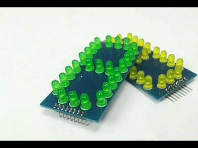
In this interesting project we will see how to create a DIY(Do it Yourself) 7 segment which is comparably larger than the traditional 7 segment available in the market.
Before diving into the DIY 7 segment let’s first understand about What is a 7 segment is and how it works.
What is 7 Segment?
A 7 Segment display is nothing but a combination of LED’s in segments. In a 7 Segment display there are 7 segments named as A, B, C, D, E, F & G.
A typical 7 Segment may be of Common Anode type or of a Common Cathode type.
In a Common Anode 7 Segment all the anode of the segments are common or we can say all the anodes are internally connected. Instead of giving individual power supply(+ve) to all the segments we can give it to the common terminal. To make a segment on we have to give individual Negative supply.
In a Common Cathode 7 Segment all the cathodes of the segments are common or we can say all the cathodes are internally connected. Instead of giving individual power supply(-ve) to all the segments we can give it to the common terminal. To make a segment on we have to give individual Positive supply.
Now we will see how you can design your own 7 Segment as per your convenience.
You can design your own PCB as per your requirement. Here we used an online tool to design our PCB.
Here is the 3D view of our Designed PCB.
Ordering PCB from JLCPCB
Ordering PCb from JLCPCB is quite simple and easy.
You just have to add your gerber file (max upto 6 layers), select layer and add to cart then checkout securely and the sum. That's it no your designed PCB is at your doorstep.
Soldering the LEDs on the PCB is quite easy. You need take care of one thing that there should not be any damage while doing.
Now our DIY 7 Segment is ready to use. Here we have designed two different color 7 Segments, you can design as per your requirement.
Now we will see how we can use our DIY 7 Segment with Arduino.
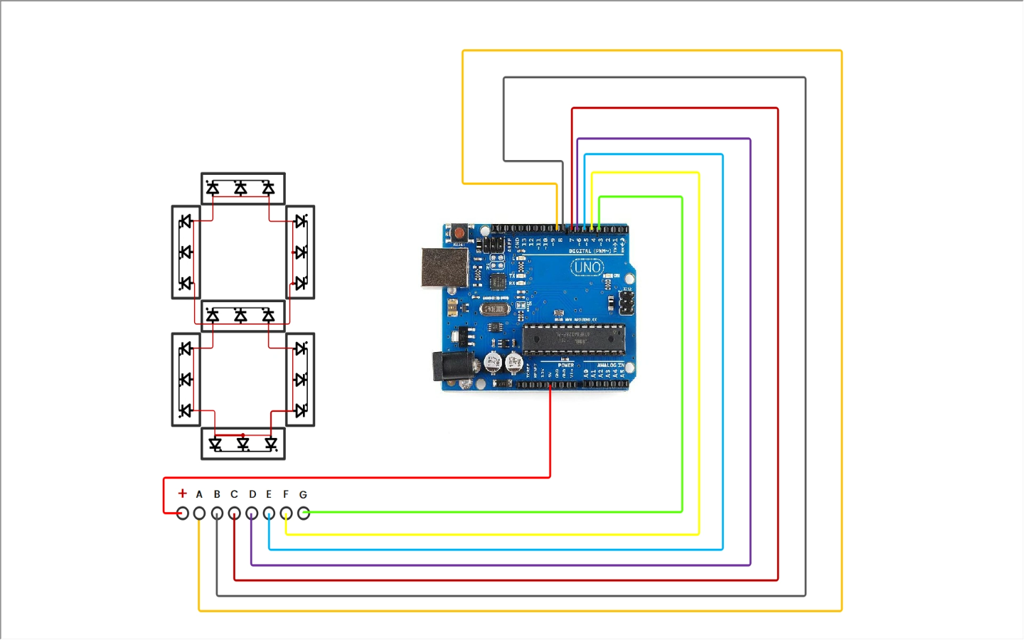
Here we have used a Common Anode 7 Segment so we connect the +5V pin of Arduino with the Common Pin of DIY 7 Segment. And all Other pins have been connected with the digital pins of Arduino. The circuit is also quite simple and easy to make.
When the circuit connection is completed upload a trial code of 7 Segments to the Arduino and Give power supply to the Arduino to make it ON.
In this article we saw how to make a DIY 7 Segment and design our own PCB. Stay tuned for more such projects….
DIY 7 Segment
Electro dude, related channels and tags.
We use cookies to provide our visitors with an optimal site experience. View our privacy notice and cookie notice to learn more about how we use cookies and how to manage your settings. By proceeding on our website you consent to the use of cookies.

How to Make Basic 7-Segment Display Connections
For experienced electronics hobbyists or professional circuit developers, incorporating a 7-segment (or larger) display into a design might be second nature. Given the plug-and-play nature of many modern devices, though, a beginner might not understand how segmented displays work. A basic overview of the design and function may help.

Basic Diodes
Each segment or point of the display uses a light emitting diode (LED), and like any common diode, there is an anode and cathode point. Connect these to a power source and ground, and the LED will light up that segment.

Common Anode and Common Cathode
The next step to understanding segmented displays is the labeling and connectivity within the unit. One end of the LEDs will have individual connections to an outside device, and the other end will join as a group to a common connection. The two connections will often be labeled as +V and GND (ground) or something very similar, and the two different configurations are referred to as ‘common cathode displays’ and ‘common anode displays’.
In the diagrams below, we can see how the orientation of the LEDs within the segmented display determines if the group connection is to +V or to GND. Note that the two connected segments (‘B’ and ‘C’ lines to the ‘1’ on the display) have the same pathway structure whether the device is common anode or common cathode given that the segments all have the same labels per device. For more information on choosing the current-limiting resistors between the display and the control signal, see the links below the drawings.
Common Cathode Display

Common Anode Display

Digi-key Tech Forum: [ Choosing the Correct Resistor for Your LED ] Digi-key Conversion Calculators [ LED Series Resistor Calculator ]
To further understand the significance of common anode and common cathode, let’s compare the number of pins that would be necessary if the +V or GND of the display was not a common (group) connection. Assume that the input side is a microcontroller using eight pins to make a path to the display (seven LED segments plus the decimal point [DP] LED = eight).
In the previous diagrams, we can see that eight display pin terminals are needed for the segments and DP, and at least one for +V or GND, for a total of nine. It is not unusual to see two pins used as +V or GND on a segmented display, but for this practice, assume only one. How would this look without the common connections? Instead of one +V/GND pin for all segments and DP, we would need one for each, for a total of eight. There would now be eight pins for one side of the LEDs, and eight pins for the other, for a total of sixteen. Clearly, this would complicate a circuit design and add extra cost to the segmented display product.

Multiplexing and Multiple Segmented Displays
What happens if there are multiple segmented displays? If we already use at least eight microcontroller pins for one display, do we need to add that many for each additional character? Multiple displays could be set up with that configuration, but much like the design without a common anode or cathode, there would be many extra terminations.
Multiplexing is a method used to overcome this problem. For this article, we are only looking at the concept and not a design plus corresponding code. In the drawing below, note the individual path to each display module, and then the common path to each segment or DP LED. Pin D11 controls the D1 display, and pin D10 controls the D0 display. On the other hand, pin D9 has double duty by controlling segment A for both displays, and D8 does the same for segment B.
The idea seems clear—turn on each display only when needed—but how are they used simultaneously? With a microcontroller and the multiplexing method, the displays are turned on and off in sequence with the segments activated as needed to display the correct character. The idea seems clear—turn on each display only when needed—but how are they used simultaneously? With a microcontroller and the multiplexing method, the displays are turned on and off in sequence with the segments activated as needed to display the correct character. Given the frequency at which a microcontroller can operate, this rapid change (refresh rate) across the characters is more than sufficient to appear stable to the human eye. This effect is know as Persistence of Vision (POV) , and refers to the image that is retained for a very short period after light from an object has ceased entering the eye.

As an experiment, one circuit could be set up using this multiplexing method, and another set up with enough MCU I/O pins to run a two-character display without multiplexing. Compare the two results versus the microcontroller resources needed to run them.
Before moving on to other ICs and methods of handling the input to a display module, check out the various microcontroller and segmented display products on the Digi-key site.
Product Index > Optoelectronics > [ Display Modules – LED Character and Numeric ]. There are filters for the ‘Number of Characters’ and ‘Display Type’ that relate to the basic topics covered here.
Product Index > Integrated Circuits (ICs) > [ Embedded – Microcontrollers ].
Binary Coded Decimal (BCD)
Are there other ways to reduce the burden on the MCU? The answer is ‘Yes’, and we’ll look at one of them, here. For this example, a basic understanding of Binary Coded Decimal is needed. It’s simply a means of converting a decimal number (0 to 9) into a four-character code that can be further translated as the segments of a display. In the following table, note the binary representation of the decimal numbers and the relation to the activated segments of a display.

There are ICs made specifically to process the BCD format into a code for a segmented display. An example is shown, below. (Depending on the IC, there may or may not be support for the DP LED, but it can also be directly controlled from the MCU.)

It may seem as though this adds more complexity to a design, but it’s usually the microcontroller that becomes overtasked, and upgrading to larger MCUs increases costs while still adding design problems. This fact becomes far more evident when looking at a basic diagram using an LED display driver such as the MAX7219 or MAX7221, below. Note that much of the work has been delegated to the display driver when using an 8-digit segmented display in the circuit, and work means resources are used. In this case, the MCU retains much of its capability to carry out other tasks.

There are display drivers on the Digi-key site that include the BCD interface: [ PMIC – Display Drivers “BCD” ].
For all of the above products and more, be sure to check out the Digi-Key home page: [ Digi-Key ]
To learn more about basic connections, read this forum post: [ Basic Keypad Connections ]
Now that we’ve covered the basic function and operation of a segmented display, we can venture into using larger models such as 14- or 16- segments for more character options. There are also more ways (and more ICs) to transfer data to the display, and some IC functions negate the need for multiplexing. On the other hand, if one needed to demonstrate the concept of segmented display operation in the simplest terms, a mechanical dip switch could be set up on the control side, and each segment would be turned on or off manually (not a bad idea for educators). The point is that there are multiple options when using a segmented display depending on one’s own skill level and the requirements of the circuit.
What is your favorite method or product? Let us know in the comments.
Further reading:
Jameco [ Identifying Light Emitting Diodes ]
Jameco [ Working with Seven Segment LED Displays ]
Adafruit [ 7-Segment Clock Display ]
Adafruit [ Blog “Segment” ]
Copyright © 1995-2022, Digi-Key Electronics. | All Rights Reserved. | Terms & Conditions | Privacy Statement
701 Brooks Avenue South, Thief River Falls, MN 56701 USA
EEVblog Electronics Community Forum

- EEVblog Electronics Community Forum »
- Electronics »
- Beginners »
- Help finding really big 7-segment LCDs

Author Topic: Help finding really big 7-segment LCDs (Read 2070 times)
0 Members and 1 Guest are viewing this topic.
- Contributor

Doctorandus_P
- Super Contributor
- Posts: 3445

Re: Help finding really big 7-segment LCDs
- Posts: 3076

- Posts: 21611
greenpossum
- Frequent Contributor

Would this work for you? http://www.e-paper-display.com/products_detail/productId=141.html
Would flip displays work? Not cheap though.
- Posts: 10576

- Posts: 5938

Quote from: james_s on September 30, 2020, 07:16:58 am Would this work for you? http://www.e-paper-display.com/products_detail/productId=141.html
- Posts: 3731

- Posts: 7096
- Posts: 1716
... Green LED displays are very efficient nowadays and a proper filter and polarizer can work in straight sun. Flip-dot displays take a huge amount of current, many amps to flip.
- SMF 2.0.19 | SMF © 2021 , Simple Machines Simple Audio Video Embedder SMFAds for Free Forums | Powered by SMFPacks Advanced Attachments Uploader Mod
Big 7-segment Digital Clock

Introduction: Big 7-segment Digital Clock

Attachments
Step 1: simple paper copy schematic.

Step 2: Collect Your Parts:

Step 3: Solder Your All Parts

Step 4: Make Your Enclosure

Step 5: Programe Your PIC16F84

Participated in the Holiday Gifts Contest
Participated in the Epilog Challenge
Recommendations

Build-A-Tool Contest

Colors of the Rainbow Contest

Text Contest


IMAGES
VIDEO
COMMENTS
First you have to create the so called outline of the PCB. This you do with the Edge-Cuts layer. On the right side of the screen select this layer (a small triangle shows the active layer) then select "add graphic lines" (4 green dots connected with blue lines) Now you can draw the outline of the PCB you want to make.
7-segment displays are useful in many electronic projects, but the 4-digit modules commonly used in Arduino or Raspberry Pi tutorials (e.g. those using TM163...
An easy to build Extendable and Reprogrammable Giant 7 Segment Display. Examples for Arduino Nano/Uno and Wemos D1 Mini (ESP8266) included. 👇 More info belo...
Treat yourself (and your neighbours) to a huge 7-Segment Display3D models and building instructions: https://www.thingiverse.com/thing:2977443Source code: ht...
The first step is to decide how big of a display you want. The foam board should be at least an inch bigger than your desired display size on all sides to give a border and place to mount it. I have had the best results cutting the foam using a sharp Exacto knife, but a good pair of scissors should suffice. 2.
Step 3: Fitting the Inlays. The easiest way, and perfectly acceptable for most uses, is to simply glue them into place flush with the front of the acrylic sheet. Super glue from the reverse side will be fine for most applications where the acrylic will not be put under any physical stresses when in use.
Lewin Day. July 27, 2022. Sometimes you need to display a number nice and large, making it easily readable at a good distance. [Lewis] has just the thing for that: a big expandable 7-segment ...
Make LED Segments. The first step is to trim your NeoPixel strip into small segments. Measure out and cut seven sections with 8 LEDs per segment. You can use scissors to cut at the line running through a three copper pad section. You should end up with four extra pixels per meter strip -- save those, you'll end up using three of them as the ...
Cool Circuit has a how-to on building large (6" high") 7-segment digital displays using 14 super-bright white LEDs. They use the PIC16F876A ... They use the PIC16F876A microcontroller and can be cascade-connected to form up to an 8-digit display. Big 7-segment - Link. Discuss this article with the rest of the community on our Discord server ...
Set this to true when using multi-digit displays. sevseg.setBrightness(90) - This function sets the brightness of the display. It can be adjusted from 0 to 100. sevseg.setNumber() - This function prints the number to the display. For example, sevseg.setNumber(4) will print the number "4" to the display.
How to Meke Homemade Large 7 Segment Display👉PCB Drawing ProgramGet a free trial of Altium Designer :👉http://www.altium.com/yt/ZAFERYILDIZ👉Subscribe to JL...
Big Time. Ever wanted to build an enormous timer using 7-segment displays? Here's a way to do just that using NeoPixel strips for the segments and acrylic diffusers to blend the individual LEDs into seamless light sources. This guide shows how to build 12" tall digits, each made from a meter of NeoPixels cut into segments and then joined at angles.
Position the 7 Segment Display so that the top row of pins are separated from the lower pins by the center gutter that divides the breadboard. Then connect a jumper wire from the resistor to pin 1 of the display. Finally, touch a jumper from the ground rail to pin 2 of the display as shown on the above diagram.
7-Segment RED 6.5″ Display @ SparkFun - Link. Of course, you could always make your own. Discuss this article with the rest of the community on our Discord server! Over at Sparkfun they're selling a relatively massive 7-segment LED display, measuring a highly legible 6"x3.3". Finally, I can see what MIDI channel I'm.
DIY Big 7-Segment Internet Display: In this project I will show you how I combined 4 inch 7-segment displays and an ESP8266 Wifi module to create an 8 digit display that can present your most important data from the internet. Let's get started! Projects Contests Teachers DIY Big 7-Segment Internet Display ...
I wanted a common-cathode display (for the MAX7219 LED display driver chip), so I also soldered all the cathodes (the short lead) for each segment together. Finally, solder wires connecting the anodes (the long lead) of each segment in the same position together (e.g. all 3 top segments, all 3 middle segments, etc). Wire it up and enjoy!
In a Common Anode 7 Segment all the anode of the segments are common or we can say all the anodes are internally connected. Instead of giving individual power supply(+ve) to all the segments we can give it to the common terminal. To make a segment on we have to give individual Negative supply. Common Cathode 7 Segment
Wire up your display for testing. ~Plug the display into your breadboard. ~Connect the two common cathodes together and attach a resistor to them. ~Connect the common cathode resistor to the -5v. ~Test each segment by connecting its pin to +5v. ~Experiment and try to make different numbers by lighting one or more segments at the same time.
A typical 7-segment LED display component, with decimal point in a wide DIP-10 package. A seven-segment display is a form of electronic display device for displaying decimal numerals that is an alternative to the more complex dot matrix displays.. Seven-segment displays are widely used in digital clocks, electronic meters, basic calculators, and other electronic devices that display numerical ...
For experienced electronics hobbyists or professional circuit developers, incorporating a 7-segment (or larger) display into a design might be second nature. Given the plug-and-play nature of many modern devices, though, a beginner might not understand how segmented displays work. A basic overview of the design and function may help. Basic Diodes Each segment or point of the display uses a ...
Here is the final result of the huge 7 segments 8 digits LED display panel: Some facts: -Total number of red LEDs: 525 pieces. -8 digits, 7 segments red LED. -Total length of LED stripe: 875 cm (one reel of 5 meters + 3,75 meters from a secondary reel) -Total current when all LEDs are on (at 12Vdc): ~2 amps.
4" LED 7-segment displays are a common size datasheet LD40011AUW shows InGaN pure green is the most efficient followed by white. Each segment is 5 LED's in series so full 20mA at 15-17V, per segment (~10V for red) which is high voltage and you would need a boost converter depending on your battery pack.
Big 7-segment Digital Clock: Using only 2 capacitors, 3 resistors, 4 BIG seven-segment Display, 1 xtal, 2 switches ,and 1 Microcontroller PIC, you can build this Digital Led Clock main circuit. you can use common anode or common cathode display, just select the display type. H…