

Human-System Integration in the System Development Process: A New Look (2007)
Chapter: 5 case studies, 5 case studies.
T his chapter provides three examples of specific system development that illustrate application of human-system integration (HSI) methods in the context of the incremental commitment model (ICM). The examples are drawn from the committee’s collective experience and specific application of the concepts developed during our work to these particular projects. They represent projects at three stages of development: the early stages of planning, in mid-development, and fully realized.
The first example involves the development of unmanned aerial systems and identifies numerous HSI issues in these systems that will require solution. This example provides a “notional” application of human factors methods and potential implementation of the incremental commitment model. The case study illustrates the theme of designing to accommodate changing conditions and requirements in the workplace. Specifically, it addresses the issue of adapting current unmanned aerial systems to accommodate fewer operators, with individual operators controlling multiple vehicles. The hypothetical solutions to this problem reveal the potential costs of reliance on automation, particularly prior to a full understanding of the domain, task, and operator strengths and limitations. This case study also reveals the tight interconnection between the various facets of human-system integration, such as manpower, personnel, training, and design. In other words, answering the “how many operators to vehicles” question necessarily impacts design, training, and personnel decisions.
The second example focuses on a large-scale government implementation of port security systems for protection against nuclear smuggling. The example discusses the HSI themes and incremental application of methods
during the iterative development of the system. This case is useful for illustrating application of human factors methods on a risk-driven basis, as they tend to be applied as needed over time in response to the iterative aspects of defining requirements and opportunities, developing design solutions, and evaluation of operational experience.
The third example describes development of an intravenous infusion pump by a medical device manufacturer. This example is the most detailed and “linear” of the three cases, in that it follows a sequential developmental process; the various systems engineering phases are discussed in terms of the human factors methods applied during each phase. This case study illustrates the successful implementation of well-known HSI methods, including contextual inquiry, prototyping and simulations, cognitive walkthroughs for estimating use-error-induced operational risks, iterative design, and usability evaluations that include testing and expert reviews. The importance of the incremental commitment model in phased decision making and the value of shared representations is also highlighted.
Each of these examples is presented in a somewhat different format, as appropriate to the type of development. This presentation emphasizes one broad finding from our study, which is that a “one size” system development model does not fit all. The examples illustrate tailored application of HSI methods, the various trade-offs that are made to incorporate them in the larger context of engineering development, and the overall theme of reducing the risk that operational systems will fail to meet user needs.
UNMANNED AERIAL SYSTEMS
Unmanned aerial systems (UASs) or remotely piloted vehicles (RPVs) are airplanes or helicopters operated remotely by humans on the ground or in some cases from a moving air, ground, or water vehicle. Until recently the term “unmanned aerial vehicle” (UAV) was used in the military services in reference to such vehicles as Predators, Global Hawks, Pioneers, Hunters, and Shadows. The term “unmanned aerial system” acknowledges the fact that the focus is on much more than a vehicle. The vehicle is only part of a large interconnected system that connects other humans and machines on the ground and in the air to carry out tasks ranging from UAS maintenance and operation to data interpretation and sensor operation. The recognition of the system in its full complexity is consistent with the evolution from human-machine design to human-system design, the topic of this report. It highlights an important theme of this book: the need for methods that are scalable to complex systems of systems.
Unmanned aerial systems are intended to keep humans out of harm’s way. However, humans are still on the ground performing maintenance, control, monitoring, and data collection functions, among others. Reports
from the Army indicate that 22 people are required on the ground to operate, maintain, and oversee a Shadow UAS (Bruce Hunn, personal communication). In addition, there is a dearth of UAS operators relative to the current need in Iraq and Afghanistan, not to mention the U.S. borders. The growing need for UAS personnel, combined with the current shortage, points to another theme of this report: the need for human-system integration to accommodate changing conditions and requirements in the workplace.
In addition, this issue has strong ties to questions of manning. The manning questions are “How many operators does it take to operate each unmanned aerial system? Can one modify the 2:1 human to machine ratio (e.g., two humans operating one UAS) to allow for a single operator and multiple aircraft (e.g., 1:4)?” Automation is often proposed as a solution to this problem, but the problem can be much more complex. Automation is not always a solution and may, in fact, present a new set of challenges, such as loss of operator situation awareness or mode confusion. Furthermore, the manning question is a good example of how HSI design touches other aspects of human-system integration, such as manpower, personnel, and training. That is, the question of how many vehicles per operator is not merely one of automation, but also involves the number and nature of the operators in question.
A Hypothetical Case
This example is based on an ongoing debate about the manning question, which has not been fully resolved. Therefore some aspects of the case are hypothetical, yet not improbable. In this example we assume that the objective of the design is to change the operator to UAS ratio from 2:1 to 1:4. That is, instead of two operators for one UAS there will be one operator for four UASs. This operator to UAS ratio is a requirement of the type that may be promulgated by the Department of Defense with minimal HSI input. It could be too late for human-system integration, which needs to be fully integrated into the engineering life cycle before system requirements have been determined. It could be too late in the sense that up-front analysis might have revealed that an effective 1:4 ratio is beyond the capabilities of current humans and technology under the best of circumstances. If this is the case, then there is a huge risk of designing a system that is doomed to fail. Even worse, this failure may not reveal itself until the right operational events line up to produce workload that breaks the system.
In our example, we present another scenario. The design of a UAS with a 1:4 ratio of operator to system is carried through the ICM development process to illustrate the potential role of human-system integration and one of the themes of this book. The Department of Defense is one of many
critical stakeholders in this scenario, all of whom are to be considered in the satisficing process that ensues.
Human-System Integration in the Context of the Incremental Commitment Model
In the earliest exploration phases of ICM development, the problem space and concept of operations are defined, and concept discovery and synthesis take place. Table 5-1 provides highlights of the entire example. It is often the case that human-system integration is not brought into the development cycle at this point, although at great risk. Up-front analyses, such as interviews of UAS operators, observations of operations of 2:1 systems, examination of mishap reports, understanding of the literature and data, an analysis of the 2:1 workload, event data analysis targeted at communications in the 2:1 UAS system, application of models of operator workload, and work flow analysis are all methods that could be used to explore the HSI issues in the current UAS system.
There is much that could come from this kind of up-front analysis. One hypothetical possibility is that the up-front HSI analyses could determine that UAS workload is not constant but peaks in target areas where photos need to be taken or in situations in which the route plan needs to change.
One of the key principles of ICM development is risk management , including risk-driven activity levels and anchor point commitment milestones. What are the risks if human-system integration is not considered early in the development life cycle? In this case, the formal requirements that are established may target workload reduction incorrectly. For example, autopilot automation might be developed to help to get multiple UASs from point A to point B and so on. This might have the effect of reducing workload when a reduction was not needed, while providing no relief from the high-workload tasks. Ultimately the neglect of up-front human-system integration could result in a system that is ineffective or prone to error. Consideration of risks like these should guide system development.
What if there is not enough time to interview UAS operators and to do a thorough job in the exploration phase? There is also risk associated with application of costly up-front techniques. The up-front methods used often during the exploration phase of the life cycle can be tailored to meet time and budget constraints—another theme of this book. For example, in this case in which the manning question is the issue and automation appears to be a promising solution, it would make sense to focus on aspects of the task that may be automated and the workload associated with each. One caveat is that decisions on how to scope and tailor the methods require some HSI expertise in order to target the aspects of human-system integration that promise the most risk reduction.
As system development progresses, other principles of ICM development come into play, including incremental growth of system development and stakeholder commitment. This part of the development life-cycle synthesis leads to construction, invention, or design that is iteratively refined as it is evaluated. HSI activities that would be useful at this point include function allocation and the development of shared representations, such as storyboards and prototypes.
Based on the previous finding of fluctuating workload, it may be decided that human intervention is needed at target areas and during route changes, but that the single operator can handle only one of these peak-workload tasks at a time. It may also be determined that, although automation could handle the routine flight task, an even more important place for automation is in the hand-off between the flight tasks and the human planning/replanning operation. The automation would therefore serve a scheduling and hand-off function, allocating complex tasks to the human operator as they arise and in order of priority (e.g., priority targets first). There could also be automation that serves as a decision aid for the targeting task.
Because only one nonroutine task can be handled at a time under the 1:4 scenario, it may also be decided that operators should be relieved of the flight functions completely but be on call for hand-offs from automation. For example, four controllers could handle the prioritized hand-offs from the automation, much as air traffic controllers handle multiple planes in a sector. Note that this new design and staffing plan are completely different in terms of operator roles and tasks from the former 2:1 operation. It is human-system integration that guided the allocation of tasks to human and machine; without it there would have been many other possibilities for automation that may not have produced the same end-state.
As the ICM development continues, the system engineers will go from working prototypes to product development, beta testing, product deployment, product maintenance, and product retirement. But there is continual iteration along the way. The incremental growth in the automation for scheduling, hand-offs, and targeting would occur in parallel with the next iteration’s requirements and subsystem definitions (i.e., concurrent engineering). Incremental growth will be influenced by stakeholder commitment. The HSI methods in the later stages include interviews and observations in conjunction with the newly designed system and usability testing. Some of the same methods used in up-front analysis (e.g., event data analysis, participatory analysis) can be again used and results contrasted with those of the earlier data collection.
The goal of human-system integration at this stage is to verify that the situation for the user has improved and that no new issues have cropped up in the interim. For instance, it may be determined from testing that the targeting decision aid is not trusted by the human operator (a stakeholder)
TABLE 5-1 Example of Human-System Integration for UASs in the Context of the Risk-Driven Spiral
and as a result is not used (a risk). Through iterations, a new design will be tested or the decision aid will be completely eliminated (i.e., stakeholder satisficing).
Conclusion and Lessons Learned
In this example, human-system integration plays a major role throughout the design process and is critical in the early stages before requirements are established. It can be integrated throughout the design life cycle with other engineering methods. It is also clear that the HSI activities serve to reduce human factors risks along the way and make evident the human factors issues that are at stake, so that these issues can be considered as they trade off with other design issues.
This example illustrates several lessons regarding human-system integration and system design:
The importance and complexity of the “system” in human-system integration compared with “machine” or “vehicle.”
Design concerns are often linked to manpower, personnel, and training concerns.
Up-front analysis and HSI input in early exploration activities is critical.
Methods can be tailored to time and money constraints, but HSI expertise is required to do so.
Risks are incurred if human-system integration is not considered or if it is considered late. In this case the risk would be a system that is not usable and that ultimately leads to catastrophic failure.
PORT SECURITY
The U.S. Department of Homeland Security (DHS) is in the process of implementing a large-scale radiation screening program to protect the country from nuclear weapons or dirty bombs that might be smuggled across the border through various ports of entry. This program encompasses all land, air, and maritime ports of entry. Our example focuses on radiation screening at seaports, which have a particularly complex operational nature. Seaports are structured to facilitate the rapid offloading of cargo containers from ocean-going vessels, provide temporary storage of the containers, and provide facilities for trucks and trains to load containers for transport to their final destination. The operation involves numerous personnel, includ-
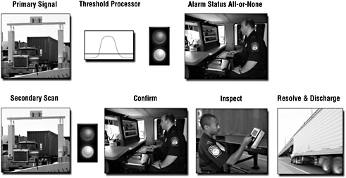
FIGURE 5-1 RPM security screening at seaports involves multiple tasks, displays, and people.
ing customs and border protection (CBP) officers for customs and security inspection, terminal personnel, such as longshoremen for equipment operation, and transport personnel, such as truck drivers and railroad operators. Figure 5-1 illustrates the steps involved in the radiation screening process.
Design and deployment of radiation portal monitoring (RPM) systems for seaport operations engages the incremental commitment model for ensuring commitments from the stakeholders and to meet the fundamental technical requirement of screening 100 percent of arriving international cargo containers for illicit radioactive material.
This example illustrates aspects of the ICM process with specific instances of human-system integration linked to concurrent technical activities in the RPM program. The development of RPM systems for application in the seaport environment entails an iterative process that reflects the overall set of themes developed in this book. We discuss how these themes are reflected in the engineering process.
Human-System Integration in the Context of Risk-Driven Incremental Commitments
The human factors design issues encountered in this program are very diverse, ranging from fundamental questions of alarm system effectiveness at a basic research level, to very practical and time-sensitive issues, such as the most appropriate methods of signage or traffic signaling for controlling
the flow of trucks through an RPM system. HSI methods have been applied on a needs-driven basis, with risk as a driver for the nature of the application. With the issue of alarm system effectiveness, for example, it was recognized early in the program that reducing system nuisance alarms is an important issue, but one that requires a considerable amount of physics research and human factors display system modeling and design. The ICM process allowed early implementation of systems with a higher nuisance alarm rate than desirable while pursuing longer term solutions to problems involving filtering, new sensors, and threat-based displays. The nuisance alarm risk was accepted for the early implementations, while concurrent engineering was performed to reduce the alarm rate and improve the threat displays for implementation in later versions.
A contrasting example involves traffic signage and signaling. Since the flow of cargo trucks through port exits is a critical element of maintaining commercial flow, yet proper speed is necessary for RPM measurement, methods for proper staging of individual vehicles needed to be developed. Most ports involve some type of vehicle checkout procedure, but this could not be relied on to produce consistent vehicle speed through the RPM systems. Instead, the program engaged the HSI specialty to assist in developing appropriate signage and signaling that would ensure truck driver attention to RPM speed requirements.
HSI Methods Tailored to Time and Budget Constraints
Since the RPM program focus is homeland security, there has been schedule urgency from the beginning. The need for rapid deployment of RPM systems to maximize threat detection and minimize commercial impact has been the key program driver, and this has also influenced how the HSI discipline has been applied. The primary effect of program urgency and budgetary limitations has been to focus HSI efforts in work domain analysis, the modeling of human-system interactions, and theory-based analysis rather than experiment.
The work domain analysis has typically focused on gaining a rapid understanding of relatively complicated seaport operations in order to evaluate technology insertion opportunities and to better understand design requirements. In contrast to work domain analysis oriented toward cognitive decision aids, which requires time-intensive collaboration with subject matter experts, the RPM analysis worked at a coarser level to characterize staff functions and interactions, material flow, and operational tempo. Similarly, modeling of human-system interactions (such as responding to a traffic light or an intercom system) was performed at the level of detail necessary to facilitate design, rather than a comprehensive representation of operator cognitive processes—this was not required to support engineering.
Theory-based analysis of alarm system effectiveness has been conducted on a somewhat longer time scale, since the problem of human response to alarms is more complex. This work consisted of adapting traditional observer-based signal detection theory, in which the human is an active component of the detection system, to RPM systems in which the human operator evaluates the output of a sensor system that detects a threat precondition. Various threat probability analyses have been conducted in this effort, and they can be used to guide subsequent advanced RPM designs. This work has been guided by empirical studies, but it has not required an independent data collection effort.
Shared Representations Used to Communicate
The rapid-paced nature of the RPM program places a premium on effective communication between human-system integration and the engineering disciplines. In this program, fairly simple communication mechanisms that use graphics or presentation methods adapted from engineering have the best chance of successful communication. For example, it is important to evaluate the human error risks associated with new security screening systems so that mitigation approaches can be designed. One approach to describing this to the engineering community might be to simply borrow existing taxonomies from researchers in the field, such as Reason (1990). Alternatively, a more graphic and less verbose approach is to represent the approach as a fault tree, shown in Figure 5-2 . This type of representation is immediately recognizable to the engineering community and is less subject to interpretation than abstract descriptions of error typologies.
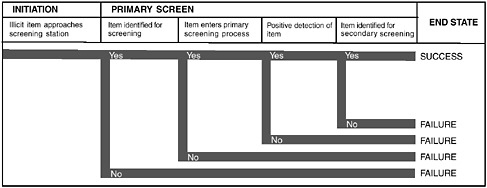
FIGURE 5-2 General model of human error analysis for security screening used as a shared representation to communicate the concept to engineering staff.
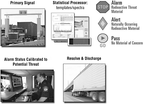
FIGURE 5-3 Graphical representation of work flow with a threat-based RPM display.
Human-system integration has used graphics to convey fairly abstract design ideas to the engineering staff, as shown in Figure 5-3 . This display conveys the concept of a threat likelihood display, which informs the RPM operator about the contents of a vehicle based on processing algorithms. The graphic contrasts the eight-step process shown in Figure 5-1 , with a four-step screening process, illustrating the functional utility of the display in a direct way.
Accommodation to Changing Conditions and Workplace Requirements
The RPM program started with a set of baseline designs for seaports that involved a cargo container passing through an exit gate. As the program expanded to a wider range of port operations, numerous variations in the container-processing operations became apparent. In some instances, the traffic volume is so low that the costs of installing a fixed installation are too high; alternatively, trenching limits or other physical constraints may preclude a fixed portal. Operational differences, such as moving containers direct to rail cars, also present challenges for design.

FIGURE 5-4 Standard truck exit RPM system (left), mobile RPM system (middle), and straddle carrier operation (right).
Figure 5-4 illustrates several variants of RPM operational configurations that have HSI implications. The truck exit shown in the figure is a standard design that accommodates the majority of seaport operations as they are currently configured. In order to accommodate reconfiguration and low volume, a mobile RPM system has been developed, as shown above. For ports at which straddle carriers are used to move containers directly to rail, solutions are currently being evaluated. Human-system integration has been directly responsible for operations studies of straddle carrier operation to discern technology insertion opportunities. The critical issue for seaports is that current operations do not predict future operations; the rapid expansion of imports will fundamentally alter how high-volume ports process their cargo, and HSI studies will be an important element of adapting the security screening technologies to evolving operational models.
Scalable Methods
The RPM program is large in scale—involving geographically distributed installations on a nationwide basis, multiple personnel, government agencies and private-sector stakeholders—and seaports are an element of
the nation’s critical infrastructure. To make an effective contribution in this context, human-system integration has focused on problems of an aggregate nature that affect multiple installations. The methods generally employed, such as work domain analysis, probabilistic risk modeling, and timeline analysis, are applicable at an individual operator, work group, or port-wide level. Scalability is inherent in the overall goals of method application (i.e., discerning general operational constraints and potential design solutions); in the process there are requirements for “one-off” tailored solutions, but the fundamental goal is to provide generic solutions.
Principles of System Development
The development of RPM systems for application in the seaport environment has entailed an iterative process that reflects the system development principles described in this book. This section discusses how these principles are reflected in the engineering process.
Success-Critical Stakeholder Satisficing
As mentioned above, this program involves the private sector (seaport terminal management and labor), local public agencies such as port authorities, local and national transportation companies such as railroads, federal government agencies (DHS), federal contractors, and, from time to time, other federal law enforcement agencies, such as the Federal Bureau of Investigation. The issues and requirements of all need to be addressed in RPM deployments. The dual program goals of maximizing threat detection and minimizing impact on commerce define the parameters for stakeholder satisficing.
Incremental Growth of System Definition and Stakeholder Commitment
The objective of minimal disruption to ongoing seaport operations and the need to identify traffic choke points and screening opportunities require considerable up-front analysis, as well as continuing evaluation of impact as individualized deployments are designed. The general activities in this category include
initial site surveys to identify choke points.
operational process analysis to identify traffic flow and screening procedures for individual seaport sites.
adaptation of baseline screening systems to specific seaport site constraints.
continued monitoring and evaluation of impact, including nuisance alarm rates and traffic flow, from design through deployment.
modification of RPM system elements as required to meet security and operational missions.
This process generally involves initial stakeholder meetings to establish the relationships necessary to adapt the technologies to individual operations. Based on information gathered in operational studies, conceptual designs (50-percent level) are proposed, reviewed, and revised as a more detailed understanding of requirements and impacts is obtained. This leads to more refined definitions of implementation requirements and operational impacts, which in turn lead to commitment at the 90-percent design review.
Risk Management
The multiple operational personnel involved in port security and seaport operations necessarily entails a variety of human factors risks when new technology is introduced. One of the major initial risks involved consideration of staffing, as customs and border protection authorities have not typically placed officers on site at seaports. A number of options for operating security equipment were evaluated, and the decision was made that CBP would staff the seaport sites with additional schedule rotations. This reduced the risk of relying on nonlaw enforcement personnel but increased the cost to the government (a trade-off). Other risks include generally low workload associated with processing alarms (a trade-off of boredom and cost, but physical presence is guaranteed), the gradual erosion of alarm credibility based on the exclusive occurrence of nuisance alarms (a trade-off of high sensitivity of detection system with potential for reduced effectiveness), risks of labor disputes as more complex technology is introduced that may be seen as infringing on private-sector territory (a trade-off of the risk of a complex labor situation with the need for security screening), and transfer of training procedure incompatibilities from one location to another (i.e., procedures vary considerably from one site to another, and staff rotate among these locations—a trade-off of procedural variability with the human ability to adapt).
HSI activities tend to be deployed in this program based on continuing assessment of risks associated with individual seaport deployments. For example, HSI operational studies of straddle carrier cargo operations were undertaken midway through seaport deployments, when it was recognized that existing technology solutions could not be adapted to that type of operation. The risk of using existing technology was that seaport operations would need to fundamentally change—this would lead to an unacceptable
impact on commerce. Thus operational studies were undertaken to identify potential technology insertion opportunities that would minimize the risk of commercial impact.
Concurrent System Definition and Development
The RPM program involves substantial concurrent engineering activity. The initial deployments have utilized relatively low-cost, high-sensitivity but low-resolution sensors made of polyvinyl toluene. These sensors are highly sensitive to radioactive material but tend to generate nuisance alarms because of low resolution of the type of radioactive material (naturally occurring versus threat material). While this yields high threat sensitivity, it is also nonspecific and creates a larger impact on commerce due to nuisance alarms and the need for secondary inspections.
However, development of advanced spectroscopic portals (ASPs) that utilize high-resolution sensors is taking place concurrently with the installation of lower resolution portals and will be deployed subsequently. These portals will be able to identify specific radioactive isotopes and will help to reduce nuisance alarms that create an adverse impact on commerce. Concurrent human factors research concerning threat-based displays will be used for developing appropriate end-user displays for the new systems.
“NEXT-GENERATION” INTRAVENOUS INFUSION PUMP
The next-generation infusion pump is a general-purpose intravenous infusion pump (IV pump) designed primarily for hospital use with secondary, limited-feature use by patients at home. The device is intended to deliver liquid medications, nutrients, blood, and other solutions at programmed flow rates, volumes, and time intervals via intravenous and other routes to a patient. The marketed name is the Symbiq™ IV Pump. The device will offer medication management features, including medication management safety software through a programmable drug library. The infuser will also have sufficient memory to support extensive tracking logs and the ability to communicate and integrate with hospital information systems. The infuser will be available as either a single-channel pump or a dual-channel pump. The two configurations can be linked together to form a 3- or 4-channel pump. The infuser includes a large touchscreen color display and can be powered by either A/C power or rechargeable batteries.
To ensure that the infuser has an easy-to-use user interface, the development of the product was based on a user-centered design approach. As part of the user-centered design approach, the team involved potential users at each phase in the design cycle. During the first phase, the team conducted interviews with potential users and stakeholders, including nurses, anes-
thesiologists, doctors, managers, hospital administrators, and biomedical technicians to gather user requirements. The team also conducted early research in the form of contextual observations and interviews in different clinical settings in hospitals as a means to understand user work flow involving infusion pumps. The information from these initial activities was used in the conceptual development phase of the next-generation infusion pump. Iterative design and evaluation took place in the development of each feature. Evaluations included interviews, usability testing in a laboratory setting, usability testing in a simulated patient environment, testing with low-fidelity paper prototypes, and testing with high-fidelity computer simulation prototypes. Computer simulations of the final user interface of each feature were used in focus groups to verify features and to obtain additional user feedback on ease of use before the final software coding began. In the final phases of development, extensive usability testing in simulated patient environments was conducted to ensure design intent has been implemented and that ease of use and usability objectives were met. Throughout the development process, iterative risk analysis, evaluation, and control were conducted in compliance with the federally regulated design control process (see Figures 5-5 and 5-6 ).
Motivation Behind the Design
The primary motivation was to design a state-of-the-art infusion pump that would be a breakthrough in terms of ease of use and improved patient safety. Over recent decades, the quality of the user interface in many IV pump designs has fallen under scrutiny due to many human factors–related issues, such as difficulty in setting up and managing a pump’s interface through careful control and display interplay. In the past 20 years, the type, shape, and use of pumps have been, from outward appearances, very similar and not highly differentiated among the different medical device manufacturers. In fall 2002, Hospira undertook a large-scale effort to redesign the IV pump. Their mission was to create a pump that was easier to set up, easier to manage, easier to oversee patient care, and easier to use safely to help the caregiver prevent medication delivery errors. There was a clear market need for a new-generation IV pump. The Institute of Medicine in 2000 estimated 98,000 deaths a year in the United States due to medical errors (Institute of Medicine, 2000).
The User-Centered Design Process in the Context of the Incremental Commitment Model
The Symbiq™ IV Pump followed a classic user-centered design process, with multiple iterations and decision gates that are typically part of the in-
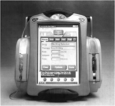
FIGURE 5-5 Two channel IV pumps with left channel illuminated. Photographs courtesy of Hospira, Inc.
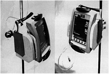
FIGURE 5-6 IV tube management features. Photographs courtesy of Hospira, Inc.
cremental commitment model of product development. Risk management was a central theme in the development, both in terms of reducing project completion and cost risks and managing the risk of adverse events to patients connected to the device. Many of the interim project deliverables, such as fully interactive simulations of graphical user interfaces (GUI), were in the form of shared representations of the design, so that all development team members had the same understanding of the product requirements during the development cycle.
Following a classic human factors approach to device design, the nurse user was the primary influence on the design of the interface and the design of the hardware. Physicians and home patient users were also included in the user profiles. Hospira embarked on a multiphase, user-centered design program that included more than 10 user studies, in-depth interviews, field observations, and numerous design reviews, each aimed at meeting the user’s expectations and improving the intelligence of the pump software aimed at preventing medication errors.
Preliminary Research
Much preliminary work needed to be done in order to kick off this development. A well-known management and marketing planning firm was hired to lead concept analysis in which the following areas were researched:
Comparison of the next-generation pump and major competitors, using traditional strengths/weaknesses/opportunities methodology, included the following features:
Physical specifications
Pump capabilities, e.g., number of channels
Programming options
Set features
Pressure capabilities
Management of air in line
Biomedical indicators
Competitive advantages of the next-generation pump were identified in the following areas:
Bar code reading capability with ergonomic reading wand
Small size and light weight
Standalone functional channels (easier work flow, flexible regarding number of pumping channels)
Extensive drug library (able to set hard and soft limits for the same drug for different profiles of use)
High-level reliability
Clear mapping of screen and pumping channels
Vertical tubing orientation that is clear and simple
An extensive competitive analysis was undertaken, against the five largest market leaders. Task flows and feature lists and capabilities were created. A prioritization of the possible competitive advantage features and their development cost estimates was generated and analyzed.
Business risks were examined using different business case scenarios and different assumptions about design with input from the outside management consultants. Engineering consultants assisted Hospira with input on technical development issues and costs, including pump mechanisms, software platforms, and display alternatives.
Extensive market research was conducted as well to identify market windows, market segment analyses, pricing alternatives, hospital purchasing decision processes, and the influence of outside clinical practice safety groups. Key leaders in critical care were assembled in focus groups and individually to assess these marketing parameters. This process was repeated. Key outcomes were put into the product concept plan and its marketing product description document. This document also captured current and future user work needs and the related environments.
The concept team reached a decision gate with the concurrence of the management steering committee. The project plan and budget were approved and development began. Again, business risks were assessed. This step is typical in an ICM development approach.
Design Decisions
A fundamental architecture decision was reached to have an integrated design with either one or two delivery channels in a single integrated unit. Two or more integrated units could themselves be connected side by side in order to obtain up to four IV channel lines. This alternate was chosen over the competing concept of having modular pumping units that would interconnect and could be stacked onto one master unit to create multiple channels. The integrated master unit approach won out based on problems uncovered from the market research, such as a higher likelihood of lost modular units, inventory problems, and reduced battery life.
Feature Needs and Their Rationale
Based on the preliminary market research and on an analysis of medical device reports from the Food and Drug Administration (FDA) as well as complaints data from the Hospira customer service organization, the Marketing Requirements Document was completed and preliminary decisions were made to include the features described in this section. Field studies and contextual inquiry were planned as follow-on research to verify the need for these features and to collect more detail on how they would be designed.
Types of programmable therapies. Decisions were made to offer a set of complex therapies in addition to the traditional simple therapies usually offered by volumetric IV pumps. The traditional simple therapies were
continuous delivery for a specified period of time (often called mL/Hr delivery).
weight-based dosing, which requires entering the patient’s weight and the ordered drug delivery rate.
bolus delivery (delivery of a dose of medication over a relatively short period of time).
piggyback delivery (the delivery type that requires Channel A delivery suspension while Channel B delivers and then its resumption when Channel B completes).
The more complex therapies included
tapered therapy (ramping up and down of a medicine with a programmed timeline. It is sometimes used for delivery of nutritional and hydration fluids, called total parenteral nutrition).
intermittent therapy (delivery of varying rates of medication at programmed time intervals).
variable time delivery.
multistep delivery.
Business risks were examined to understand the sales consequences of including these features of therapy types to address the issue of stakeholder satisficing.
Medication libraries with hard and soft dosage limits. Research uncovered that several outside patient safety advocate agencies, including the Emergency Care Research Institute and the Institute for Safe Medical Practices were recommending only IV pumps with safety software consisting of upper and lower dosage limits for different drugs as a function of the
programmed clinical care area in a hospital. (Clinical care areas include emergency room, intensive care unit, oncology, pediatrics, transplants, etc.) It became clear that it would have been imperative to have safety software in the form of medication libraries that were programmed by each hospital to have soft limits (which could be overridden by nurses with permission codes) and hard limits (that could under no circumstances be overridden). It was decided at this time that separate software applications would need to written that would be used by hospital pharmacy and safety committees to enter drugs in a library table with these soft and hard limits, which would vary by clinical care area in the hospital. This is an example of incremental growth and stakeholder commitment in the design process.
Large color touch screen. A human factors literature review was conducted to create a list of advantages and disadvantages of various input and display technologies. This research was supplemented with engineering data on the costs and reliabilities of these technologies. Again, business risks were examined, including reliability of supply of various display vendors. After much research and debate, the list of choices was narrowed to three vendors of touch-sensitive color LCD displays.
This was a breakthrough, in the sense that no current on-market IV pumps were using color touchscreen technology. A large 8.4-inch diagonal color LCD display with resistive touchscreen input was selected for further testing. A resistive touchscreen was believed to reduce errors due to poor screen response to light finger touch forces.
Another issue that required some data from use environment analysis was the required angle of view and display brightness under various use scenarios. Subsequent contextual inquiry data did verify the need for viewing angles of at least +/- 60 degrees horizontal viewing and +/- 30 degrees vertical viewing angles. The minimum brightness or luminance levels were verified at 35 candelas per square meter. A business risk analysis examined the trade-offs between a large touchscreen display and the conflicting customer desire for small footprint IV pumps. The larger display size of 8.4-inch diagonal would allow larger on-screen buttons to minimize use errors due to inadvertent selection of adjacent on-screen buttons as well as allowing larger more readable on-screen text. Again, human factors research literature and standards on display usability were included in these decisions.
Special alarms with melodies. FDA medical device reports and customer complaint data reinforced the need for more effective visual and auditory alarms to alert IV pump users to pump fault conditions, such as air in line, occlusion in IV tubing, pending battery failure, IV bag nearly empty or unsafe dosage rates for a particular drug in a specific critical care area.
The team also decided to adopt the recommendations of the International Electrotechnical Commission (IEC) for an international standard for medical device auditory alarms to use unique melody patterns for IV pumps to distinguish these devices from other critical care devices, such as ventilators and vital sign patient monitors. These auditory alarms were later subjected to extensive lab and field studies for effectiveness and acceptability.
An early beta test in actual hospital settings with extended use subsequently showed user dissatisfaction with the harshness of some of the alarm melodies. The IEC standard had purposely recommended a discordant set of tone melodies for the highest alarm level, but clinicians, patients, and their families complained that they were too harsh and irritating. Some clinicians complained that they would not use these IV pumps at all, unless the alarms were modified. Or worse, they would permanently disable the alarms, which would create a very risky use environment.
This outcome highlights a well-known dilemma for human factors: lab studies are imperfect predictors of user behavior and attitudes in a real-world, extended-use setting. The previous lab usability studies were by their very nature short-duration exposures to these tones and showed that they were effective and alerting, but they did not capture long-term subjective preference ratings. A tone design specialist was engaged who redesigned the tones to be more acceptable, while still being alerting, attention grabbing, and still in compliance with the IEC alarm standard for melodies. Subsequent comparative usability evaluations (group demonstrations and interviews) demonstrated the acceptability of the redesigned melodies. This is a prime example of design iteration and concurrent system definition and development.
Semiautomatic cassette loading. Another early decision involved choosing between a traditional manual loading of the cassette into the IV pump or a semiautomated system, in which a motor draws a compartment into the pumping mechanism, after the clinician initially places the cassette into the loading compartment. The cassette is in line with the IV tubing and IV bag containing the medication. The volumetric pumping action is done through mechanical fingers, which activate diaphragms in the plastic cassette mechanism. Customer complaint history suggested the need for the semiautomated system to avoid use error in loading the cassette and to provide a fail-safe mechanism to close off flow in the IV line except when it was inserted properly into the IV pump.
A major problem with earlier cassette-based volumetric IV pump systems was the problem of “free flow,” in which medication could flow uncontrolled into a patient due to gravitational forces, with the possibility of severe adverse events. Early risk analysis and evaluation were done from both a business and use-error safety perspective to examine the benefit of
the semiautomated loading mechanism. Later usability testing and mechanical bench testing validated the decision to select the semiautomated loading feature.
A related decision was to embed a unique LED-based lighting indication system into the cassette loading compartment that would signal with colored red, yellow, and green lights and steady versus flashing conditions the state of the IV pump in general and specifically of the cassette loading mechanism. The lights needed to be visible from at least 9 feet to indicate that the IV pump is running normally, pump is stopped, cassette is improperly loaded, cassette compartment drawer is in the process of activation, etc.
Special pole mounting hardware. Again, data from the FDA medical device reports and customer complaints indicated the need for innovative mechanisms for the mounting of the IV pump on poles. Later contextual inquiry and field shadowing exercises validated the need for special features allowing for the rapid connection and dismounting of the IV pump to the pole via quick release/activation mechanisms that employed ratchet-like slip clutches. Subsequent ergonomics-focused usability tests of hardware mechanisms validated the need and usability of these design innovations for mounting on both IV poles and special bed-mounted poles, to accommodate IV pumps while a patient’s bed is being moved from one hospital department to another.
Risk analyses for business and safety risks were updated to include these design decisions. Industrial design models were built to prototype these concepts, and these working prototypes were subjected to subsequent lab-based usability testing. Again, these actions are examples of stakeholder satisficing, incremental growth of system definition, and iterative system design.
Stacking requirements. Given the earlier conceptual design decision to have an integrated IV pump rather than using add-on pumping channel modules, decisions were needed on how integrated IV pumps could be stacked together to create additional channels. A concomitant decision was that the integrated IV pump would be offered with either one or two integrated channels. Based on risk assessment, it was decided to allow side-by-side stacking to allow the creation of a 4-channel system when desired. The 4-channel system would be electronically integrated and allow the user interface to operate as one system. Again, trade-off analyses of risks were made against the competing customer need for a smaller device size footprint. A related design decision was to have an industrial design that allowed handles for easy transportation, but would also allow stable vertical stacking, while the units are stored between uses in the biomedi-
cal engineering department. Market research clearly indicated the need for vertical stacking in crowded storage areas. To facilitate safe storage of the pumps, the special pole clamps were made removable.
Tubing management. A well-known use-error problem of tangled and confusing IV tubing lines was addressed in the housing design by including several holders for storing excess tubing. Notches were also included to keep tubes organized and straight to reduce line-crossing confusion. These same holders were built as slight protrusions that protected the touchscreen from damage and inadvertent touch activation, if the pump were to be laid on its side or brushed against other medical devices.
Many other preliminary design decisions were made in these early stages that were based on both business and use-error risk analysis. In all cases, these decisions were verified and validated with subsequent data from usability tests and from field trials.
Design Process Details
The development of the Symbiq™ IV Pump followed the acknowledged best practices iterative user-centered design process as described in medical device standards (ANSI/AAMI HE 74:2001, IEC 60601-1-6:2004, and FDA human factors guidance for medical device design controls). The following sections are brief descriptions of what was done. Table 5-2 outlines the use of these human factors techniques and some areas for methodology improvements.
Contextual Inquiry
Contextual inquiry was done by multiple nurse shadowing visits to the most important clinical care areas in several representative hospitals. Several team members spent approximately a half-day shadowing nurses using IV pumps and other medical devices and observing their behaviors and problems. A checklist was used to record behaviors and, as time permitted, ask about problem areas with IV pumps and features that needed attention during the design process. Subsequent to the field visits, one-on-one interviews with nurses were conducted to explore in depth the contextual inquiry observations. These observations and interviews were used to generate the following elements:
task analyses
use environment analyses
user profiles analyses
Figure 5-7 shows an example of one of many task flow diagrams generated during the task analyses phases of the contextual inquiry.
Setting Usability Objectives
Quantitative usability objectives were set based on data from the contextual inquiry, user interviews, and the previous market research. Early use-error risk analysis highlighted tasks that were likely to have high risk, with particular attention to setting usability objectives to ensure that these user interface design mitigations were effective. Experience with earlier IV pump designs and user performance in usability tests also influenced the setting of these usability objectives. The objectives were primarily based on successful task performance measures and secondarily on user satisfaction measures. Examples of usability objectives were
90 percent of experienced nurses would be able to insert the cassette the first time while receiving minimal training; 99 percent would be able to correct any insertion errors.
90 percent of first-time users with no training would be able to power the pump off when directed.
90 percent of experienced nurses would be able to clear an alarm within 1 minute as first-time users with minimal training.
80 percent of patient users would rate the overall ease of use of the IV pump 3 or higher on a 5-point scale of satisfaction with 5 being the highest value.
Early Risk Management
Many rounds of iterative risk analysis, risk evaluation, and risk control were initiated at the earliest stages of design. The risk-management process followed recognized standards in the area of medical device design (e.g., ISO 14971:2000, see International Organization for Standardization, 2000a). The risk analysis process was documented in the form of a failure modes and effects analysis (FMEA), which is described in more detail in Chapter 8 . Table 5-3 presents excerpts from the early Symbiq™ FMEA. Business and project completion risks were frequently addressed at phase review and management review meetings.
The concept of risk priority number (RPN) was used in the operation risk assessment for the Symbiq™ infusion system. RPN is the resulting product of multiplying fault probability times risk hazard severity times probability of detecting the fault. A maximum RPN value is typically 125, and decision rules require careful examination of mitigation when the RPN
TABLE 5-2 Methodology Issues and Research Needs
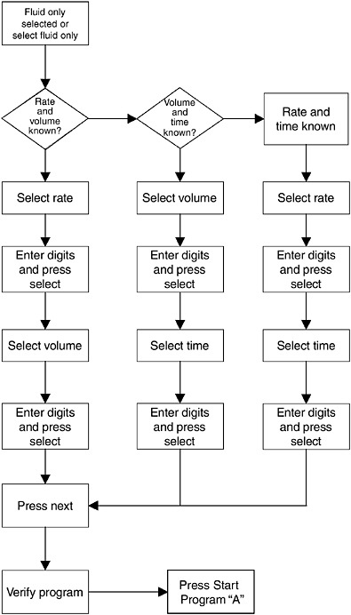
FIGURE 5-7 Illustrative task flow diagram from the task analysis.
values exceed a value of 45. RPN values between 8 and 45 require an explanation or justification of how the risk is controlled.
The product requirements document (PDR) was formally created at this point to describe the details of the product design. It was considered a draft for revision as testing and other data became available. It was based on the customer needs expressed in the marketing requirements document. This document recorded the incremental growth of system definitions and stakeholder commitment and served as a shared representation of the design requirements for the development team.
Many prototypes and simulations were created for evaluation:
Hardware models and alternatives considered
hardware industrial design mock-ups
early usability tests of hardware mock-ups.
Paper prototypes for graphical user interfaces with wireframes consisting of basic shapes, such as boxes and buttons without finished detail graphic elements.
GUI simulations using Flash™ animations. 1
Early usability tests with hardware mock-ups and embedded software that delivered the Flash™ animations to a touchscreen interface that was integrated into the hardware case.
Flash animations are excellent examples of shared representations because they were directly used in the product requirements document to specify to software engineering exactly how the GUI was to be developed. All team discussions regarding GUI design were focused exclusively on the Flash animation shared representations of the Symbiq™ user interface.
Integrated Hardware and Software Models with Integrated Usability Tests
As noted earlier, the usability tests performed later in the development cycle were done with integrated hardware mock-ups and software simulations. Usability test tasks were driven by tasks with high-risk index values in the risk analysis, specifically the FMEA. Tasks were also included that had formal usability objectives associated with them. Although the majority of usability test tasks were focused on the interaction with the touchscreen-
TABLE 5-3 Excerpts from Symbiq™ Failure Modes and Effects Analysis (FMEA)
based graphical user interface, critical pump-handling tasks were included as well, such as IV pump mounting and dismounting on typical IV poles.
Tests of Alarm Criticality and Alerting
The initial alarm formative usability studies, described earlier, had the goal of selecting alarms that would be alerting, attention getting, and properly convey alarm priority, as well as communicating appropriate actions. These formative studies evaluated the subject’s abilities to identify and dis-
criminate among different visual alarm dimensions, including colors, flash rates, and text size and contrast. For auditory alarms, subjects were tested on their ability to discriminate among various tones with and without melodies and among various cadences and tone sequences for priority levels and detectability. Subjects were asked to rate the candidate tones relative to a standard tone, which was given a value of 100. The standard was the alternating high-low European-style police siren. Subjective measures were also gathered on the tones using the PAD rating system, standing for perceived tone pleasure, arousal, and dominance, as well as perceived criticality. Data
from these studies enabled the team to make further incremental decisions on system definitions for both visual and auditory alarms and alerts.
Tests of Display Readability
Another set of early formative usability tests was conducted to validate the selection of the particular LCD touchscreen for readability and legibility. During the evaluation it was determined that the screen angle (75 degrees) and overall curvature were acceptable. The screen could be read in all tested light conditions at a 15-foot viewing distance.
Iterative Usability Tests
As noted, a series of 10 usability studies were conducted iteratively as the design progressed from early wireframes to the completed user interface with all the major features implemented in a working IV pump. In one of the intermediate formative usability tests, a patient simulator facility was used at a major teaching hospital. Users performed a variety of critical tasks in a simulated room in an intensive care unit, in which other medical devices interacted and produced noises and other distractions. The prototype IV pump delivered fluid to a mannequin connected to a patient monitor that included all vital signs. As the pump was programmed and subsequently changed (e.g., doses titrated), the software-controlled patient mannequin would respond accordingly. The patient simulator also introduced ringing telephones and other realistic conditions during the usability test. This test environment helped in proving the usability of visual alarms and tones, as well as the understandability and readability of the visual displays. Final summative usability tests demonstrated that the usability objectives for the pump were achieved.
Focus Groups
Focus groups of nurses were also used as part of the usability evaluation process. These were used to complement the task-based usability tests. Many of the focus groups had a task performance component. Typically the participants would perform some tasks with new and old versions of design changes, such as time entry widgets on the touchscreen, and then convene to discuss and rate their experiences. This allowed a behavioral component and addressed one of the major shortcomings of typical focus groups, that they focus only on opinions and attitudes and not behaviors.
Field Studies
Field studies in the form of medical device studies have also been incorporated in the design process. Thoroughly bench-tested and working beta versions of the IV pump were deployed in two hospital settings. The hospitals programmed drug libraries for at least two clinical care areas. The devices were used for about 4 weeks. Surveys and interviews were conducted with the users to capture their real-world experiences with the pump. Data from the pump usage and interaction memory were also analyzed and compared with original doctor’s orders. This study revealed a number of opportunities to make improvements, including the problem with the perceived annoyance of the alarm melodies and the data entry methods for entering units of medication delivery time (e.g., hours or minutes).
Instructions for Use Development and Testing
Usability testing was also conducted on one of the sets of abbreviated instructions called TIPS cards. These cards serve as reminders for how to complete the most critical tasks. These usability studies involved 15 experienced nurses with minimal instructions performing 9 tasks with the requirement that they read and use the TIPS cards. Numerous suggestions for improvement in the TIPS cards themselves as well as the user interface came from this work, including how to reset the air-in-line alarm and how to address the alarm and check all on-screen help text for accuracy.
Validation Usability Tests
Two rounds of summative usability testing were conducted, again with experienced nurses performing critical tasks identified during the task analysis, including those with higher risk values in the risk analysis. The tasks were selected to simulate situations that the nurses may encounter while using the IV pump in a hospital setting. The tasks included selecting a clinical care area, programming simple deliveries, adding more volume at the end of an infusion, setting a “near end of infusion” alarm, titration, dose calculations, piggyback deliveries, intermittent deliveries, using standby, programming a lock, adjusting the alarm volume, and responding to messages regarding alarms.
Usability objectives were used as acceptance criteria for the summative validation usability tests. The study objectives were met. The calculated task completion accuracy was 99.66 percent for all tasks for first-time nurse users with minimal training. The null hypothesis that 80 percent of the participants would rate the usability 3 or higher on a 5-point scale in the overall categories was met. There were a few minor usability problems
uncovered that were subsequently fixed without major changes to the user interface or that affected critical safety-related tasks.
Federal regulations on product design controls require that a product’s user interface be validated with the final working product in a simulated work environment. In this instance, the working product was used in a laboratory test, but without having the device connected to an actual patient. Bench testing is also a part of validation to ensure that all mechanical and electrical specifications and requirements have been met.
Revised Risk Analysis
As part of the incremental commitment model, the risk analysis was iterated and revised as the product development matured. FMEAs were updated for three product areas, which were safety-critical risks associated with the user interface, the mechanical and electrical subsystems, and the product manufacturing process. Explicit analysis of the business risks and the costs of continued financial commitment to the funding of development were also incremented and reviewed at various management and phase reviews.
Product Introduction
Product introduction planning included data collection from initial users to better understand remaining usage issues that can be uncovered only during prolonged usage in realistic clinical conditions. The many cycles of laboratory-based usability testing typically are never detailed enough or long enough to uncover all usability problems. The plan is to use the company complaint handling and resolution process (e.g., corrective action and preventive action) to address use issues if they arise after product introduction.
Life-Cycle Planning
The product was developed as a platform for the next generation of infusion pump products. As such, there will be continued business risk assessment during the life cycle of this first product on the new platform as well as on subsequent products and feature extensions.
Summary of Design Issues and Methods Used
This infusion pump incorporated the best practices of user-centered design in order to address the serious user interface deficiencies of previous infusion pumps. The development process took excellent advantage of the
detailed amount of data that is derived from an integrated HSI approach and used it to improve and optimize the safety and usability of the design. Because of these efforts, the Symbiq™ IV Pump won the 2006 Human Factors and Ergonomics Society award for best new product design from the product design technical group.
This case study also illustrates and incorporates the central themes of this report:
Human-system integration must be an integral part of systems engineering.
Begin HSI contributions to development early and continue them throughout the development life cycle.
Adopt a risk-driven approach to determining needs for HSI activity (multiple applications of risk management to both business and safety risks).
Tailor methods to time and budget constraints (scalability).
Ensure communication among stakeholders of HSI outputs (shared representations).
Design to accommodate changing conditions and requirements in the workplace (the use of iterative design and the incremental commitment model).
This case study also demonstrates the five key principles that are integral parts of the incremental commitment model of development: (1) stakeholder satisficing, (2) incremental growth of system definition and stakeholder commitment, (3) iterative system development, (4) concurrent system definition and development, and (5) risk management—risk-driven activity levels.
This page intentionally left blank.
In April 1991 BusinessWeek ran a cover story entitled, "I Can't Work This ?#!!@ Thing," about the difficulties many people have with consumer products, such as cell phones and VCRs. More than 15 years later, the situation is much the same—but at a very different level of scale. The disconnect between people and technology has had society-wide consequences in the large-scale system accidents from major human error, such as those at Three Mile Island and in Chernobyl.
To prevent both the individually annoying and nationally significant consequences, human capabilities and needs must be considered early and throughout system design and development. One challenge for such consideration has been providing the background and data needed for the seamless integration of humans into the design process from various perspectives: human factors engineering, manpower, personnel, training, safety and health, and, in the military, habitability and survivability. This collection of development activities has come to be called human-system integration (HSI). Human-System Integration in the System Development Process reviews in detail more than 20 categories of HSI methods to provide invaluable guidance and information for system designers and developers.
READ FREE ONLINE
Welcome to OpenBook!
You're looking at OpenBook, NAP.edu's online reading room since 1999. Based on feedback from you, our users, we've made some improvements that make it easier than ever to read thousands of publications on our website.
Do you want to take a quick tour of the OpenBook's features?
Show this book's table of contents , where you can jump to any chapter by name.
...or use these buttons to go back to the previous chapter or skip to the next one.
Jump up to the previous page or down to the next one. Also, you can type in a page number and press Enter to go directly to that page in the book.
Switch between the Original Pages , where you can read the report as it appeared in print, and Text Pages for the web version, where you can highlight and search the text.
To search the entire text of this book, type in your search term here and press Enter .
Share a link to this book page on your preferred social network or via email.
View our suggested citation for this chapter.
Ready to take your reading offline? Click here to buy this book in print or download it as a free PDF, if available.
Get Email Updates
Do you enjoy reading reports from the Academies online for free ? Sign up for email notifications and we'll let you know about new publications in your areas of interest when they're released.
Part II: Information Systems for Strategic Advantage
Chapter 10: Information Systems Development
Learning Objectives
Upon successful completion of this chapter, you will be able to:
- Explain the overall process of developing new software;
- Explain the differences between software development methodologies;
- Understand the different types of programming languages used to develop software;
- Understand some of the issues surrounding the development of websites and mobile applications; and
- Identify the four primary implementation policies.
Introduction
When someone has an idea for a new function to be performed by a computer, how does that idea become reality? If a company wants to implement a new business process and needs new hardware or software to support it, how do they go about making it happen? This chapter covers the different methods of taking those ideas and bringing them to reality, a process known as information systems development.
Programming
Software is created via programming, as discussed in Chapter 2. Programming is the process of creating a set of logical instructions for a digital device to follow using a programming language. The process of programming is sometimes called “coding” because the developer takes the design and encodes it into a programming language which then runs on the computer.
The process of developing good software is usually not as simple as sitting down and writing some code. Sometimes a programmer can quickly write a short program to solve a need, but in most instances the creation of software is a resource-intensive process that involves several different groups of people in an organization. In order to do this effectively, the groups agree to follow a specific software development methodology. The following sections review several different methodologies for software development, as summarized in the table below and more fully described in the following sections.

Systems Development Life Cycle
The Systems Development Life Cycle (SDLC) was first developed in the 1960s to manage the large software projects associated with corporate systems running on mainframes. This approach to software development is very structured and risk averse, designed to manage large projects that include multiple programmers and systems that have a large impact on the organization. It requires a clear, upfront understanding of what the software is supposed to do and is not amenable to design changes. This approach is roughly similar to an assembly line process, where it is clear to all stakeholders what the end product should do and that major changes are difficult and costly to implement.
Various definitions of the SDLC methodology exist, but most contain the following phases.
- Preliminary Analysis. A request for a replacement or new system is first reviewed. The review includes questions such as: What is the problem-to-be-solved? Is creating a solution possible? What alternatives exist? What is currently being done about it? Is this project a good fit for our organization? After addressing these question, a feasibility study is launched. The feasibility study includes an analysis of the technical feasibility, the economic feasibility or affordability, and the legal feasibility. This step is important in determining if the project should be initiated and may be done by someone with a title of Requirements Analyst or Business Analyst
- System Analysis. In this phase one or more system analysts work with different stakeholder groups to determine the specific requirements for the new system. No programming is done in this step. Instead, procedures are documented, key players/users are interviewed, and data requirements are developed in order to get an overall impression of exactly what the system is supposed to do. The result of this phase is a system requirements document and may be done by someone with a title of Systems Analyst
- System Design. In this phase, a designer takes the system requirements document created in the previous phase and develops the specific technical details required for the system. It is in this phase that the business requirements are translated into specific technical requirements. The design for the user interface, database, data inputs and outputs, and reporting are developed here. The result of this phase is a system design document. This document will have everything a programmer needs to actually create the system and may be done by someone with a title of Systems Analyst, Developer, or Systems Architect, based on the scale of the project.
- Programming. The code finally gets written in the programming phase. Using the system design document as a guide, programmers develop the software. The result of this phase is an initial working program that meets the requirements specified in the system analysis phase and the design developed in the system design phase. These tasks are done by persons with titles such as Developer, Software Engineer, Programmer, or Coder.
- Testing. In the testing phase the software program developed in the programming phase is put through a series of structured tests. The first is a unit test, which evaluates individual parts of the code for errors or bugs. This is followed by a system test in which the different components of the system are tested to ensure that they work together properly. Finally, the user acceptance test allows those that will be using the software to test the system to ensure that it meets their standards. Any bugs, errors, or problems found during testing are resolved and then the software is tested again. These tasks are done by persons with titles such as Tester, Testing Analyst, or Quality Assurance.
- Implementation. Once the new system is developed and tested, it has to be implemented in the organization. This phase includes training the users, providing documentation, and data conversion from the previous system to the new system. Implementation can take many forms, depending on the type of system, the number and type of users, and how urgent it is that the system become operational. These different forms of implementation are covered later in the chapter.
- Maintenance. This final phase takes place once the implementation phase is complete. In the maintenance phase the system has a structured support process in place. Reported bugs are fixed and requests for new features are evaluated and implemented. Also, system updates and backups of the software are made for each new version of the program. Since maintenance is normally an Operating Expense (OPEX) while much of development is a Capital Expense (CAPEX), funds normally come out of different budgets or cost centers.

The SDLC methodology is sometimes referred to as the waterfall methodology to represent how each step is a separate part of the process. Only when one step is completed can another step begin. After each step an organization must decide when to move to the next step. This methodology has been criticized for being quite rigid, allowing movement in only one direction, namely, forward in the cycle. For example, changes to the requirements are not allowed once the process has begun. No software is available until after the programming phase.
Again, SDLC was developed for large, structured projects. Projects using SDLC can sometimes take months or years to complete. Because of its inflexibility and the availability of new programming techniques and tools, many other software development methodologies have been developed. Many of these retain some of the underlying concepts of SDLC, but are not as rigid.
Rapid Application Development

Rapid Application Development (RAD) focuses on quickly building a working model of the software, getting feedback from users, and then using that feedback to update the working model. After several iterations of development, a final version is developed and implemented.
The RAD methodology consists of four phases.
- Requirements Planning. This phase is similar to the preliminary analysis, system analysis, and design phases of the SDLC. In this phase the overall requirements for the system are defined, a team is identified, and feasibility is determined.
- User Design. In the user design phase representatives of the users work with the system analysts, designers, and programmers to interactively create the design of the system. Sometimes a Joint Application Development (JAD) session is used to facilitate working with all of these various stakeholders. A JAD session brings all of the stakeholders for a structured discussion about the design of the system. Application developers also participate and observe, trying to understand the essence of the requirements.
- Construction. In the construction phase the application developers, working with the users, build the next version of the system through an interactive process. Changes can be made as developers work on the program. This step is executed in parallel with the User Design step in an iterative fashion, making modifications until an acceptable version of the product is developed.
- Cutover. Cutover involves switching from the old system to the new software. Timing of the cutover phase is crucial and is usually done when there is low activity. For example, IT systems in higher education undergo many changes and upgrades during the summer or between fall semester and spring semester. Approaches to the migration from the old to the new system vary between organizations. Some prefer to simply start the new software and terminate use of the old software. Others choose to use an incremental cutover, bringing one part online at a time. A cutover to a new accounting system may be done one module at a time such as general ledger first, then payroll, followed by accounts receivable, etc. until all modules have been implemented. A third approach is to run both the old and new systems in parallel, comparing results daily to confirm the new system is accurate and dependable. A more thorough discussion of implementation strategies appears near the end of this chapter.
As you can see, the RAD methodology is much more compressed than SDLC. Many of the SDLC steps are combined and the focus is on user participation and iteration. This methodology is much better suited for smaller projects than SDLC and has the added advantage of giving users the ability to provide feedback throughout the process. SDLC requires more documentation and attention to detail and is well suited to large, resource-intensive projects. RAD makes more sense for smaller projects that are less resource intensive and need to be developed quickly.
Agile Methodologies
Agile methodologies are a group of methodologies that utilize incremental changes with a focus on quality and attention to detail. Each increment is released in a specified period of time (called a time box), creating a regular release schedule with very specific objectives. While considered a separate methodology from RAD, the two methodologies share some of the same principles such as iterative development, user interaction, and flexibility to change. The agile methodologies are based on the “ Agile Manifesto ,” first released in 2001.

Agile and Iterative Development
The diagram above emphasizes iterations in the center of agile development. You should notice how the building blocks of the developing system move from left to right, a block at a time, not the entire project. Blocks that are not acceptable are returned through feedback and the developers make the needed modifications. Finally, notice the Daily Review at the top of the diagram. Agile Development means constant evaluation by both developers and customers (notice the term “Collaboration”) of each day’s work.
The characteristics of agile methodology include:
- Small cross-functional teams that include development team members and users;
- Daily status meetings to discuss the current state of the project;
- Short time-frame increments (from days to one or two weeks) for each change to be completed; and
- Working project at the end of each iteration which demonstrates progress to the stakeholders.
The goal of agile methodologies is to provide the flexibility of an iterative approach while ensuring a quality product.
Lean Methodology

One last methodology to discuss is a relatively new concept taken from the business bestseller The Lean Startup by Eric Reis. Lean focuses on taking an initial idea and developing a Minimum Viable Product (MVP). The MVP is a working software application with just enough functionality to demonstrate the idea behind the project. Once the MVP is developed, the development team gives it to potential users for review. Feedback on the MVP is generated in two forms. First, direct observation and discussion with the users and second, usage statistics gathered from the software itself. Using these two forms of feedback, the team determines whether they should continue in the same direction or rethink the core idea behind the project, change the functions, and create a new MVP. This change in strategy is called a pivot. Several iterations of the MVP are developed, with new functions added each time based on the feedback, until a final product is completed.
The biggest difference between the iterative and non-iterative methodologies is that the full set of requirements for the system are not known when the project is launched. As each iteration of the project is released, the statistics and feedback gathered are used to determine the requirements. The lean methodology works best in an entrepreneurial environment where a company is interested in determining if their idea for a program is worth developing.
Sidebar: The Quality Triangle

When developing software or any sort of product or service, there exists a tension between the developers and the different stakeholder groups such as management, users, and investors. This tension relates to how quickly the software can be developed (time), how much money will be spent (cost), and how well it will be built (quality). The quality triangle is a simple concept. It states that for any product or service being developed, you can only address two of the following: time, cost, and quality.
So why can only two of the three factors in the triangle be considered? Because each of these three components are in competition with each other! If you are willing and able to spend a lot of money, then a project can be completed quickly with high quality results because you can provide more resources towards its development. If a project’s completion date is not a priority, then it can be completed at a lower cost with higher quality results using a smaller team with fewer resources. Of course, these are just generalizations, and different projects may not fit this model perfectly. But overall, this model is designed to help you understand the trade-offs that must be made when you are developing new products and services.
There are other, fundamental reasons why low-cost, high-quality projects done quickly are so difficult to achieve.
- The human mind is analog and the machines the software run on are digital. These are completely different natures that depend upon context and nuance versus being a 1 or a 0. Things that seem obvious to the human mind are not so obvious when forced into a 1 or 0 binary choice.
- Human beings leave their imprints on the applications or systems they design. This is best summed up by Conway’s Law (1968) – “Organizations that design information systems are constrained to do so in a way that mirrors their internal communication processes.” Organizations with poor communication processes will find it very difficult to communicate requirements and priorities, especially for projects at the enterprise level (i.e., that affect the whole organization.
Programming Languages
As noted earlier, developers create programs using one of several programming languages. A programming language is an artificial language that provides a way for a developer to create programming code to communicate logic in a format that can be executed by the computer hardware. Over the past few decades, many different types of programming languages have evolved to meet a variety of needs. One way to characterize programming languages is by their “generation.”
Generations of Programming Languages
Early languages were specific to the type of hardware that had to be programmed. Each type of computer hardware had a different low level programming language. In those early languages very specific instructions had to be entered line by line – a tedious process.
First generation languages were called machine code because programming was done in the format the machine/computer could read. So programming was done by directly setting actual ones and zeroes (the bits) in the program using binary code. Here is an example program that adds 1234 and 4321 using machine language:
Assembly language is the second generation language and uses English-like phrases rather than machine-code instructions, making it easier to program. An assembly language program must be run through an assembler, which converts it into machine code. Here is a sample program that adds 1234 and 4321 using assembly language.
Third-generation languages are not specific to the type of hardware on which they run and are similar to spoken languages. Most third generation languages must be compiled. The developer writes the program in a form known generically as source code , then the compiler converts the source code into machine code, producing an executable file. Well-known third generation languages include BASIC, C, Python, and Java. Here is an example using BASIC:
Fourth generation languages are a class of programming tools that enable fast application development using intuitive interfaces and environments. Many times a fourth generation language has a very specific purpose, such as database interaction or report-writing. These tools can be used by those with very little formal training in programming and allow for the quick development of applications and/or functionality. Examples of fourth-generation languages include: Clipper, FOCUS, SQL, and SPSS.
Why would anyone want to program in a lower level language when they require so much more work? The answer is similar to why some prefer to drive manual transmission vehicles instead of automatic transmission, namely, control and efficiency. Lower level languages, such as assembly language, are much more efficient and execute much more quickly. The developer has finer control over the hardware as well. Sometimes a combination of higher and lower level languages is mixed together to get the best of both worlds. The programmer can create the overall structure and interface using a higher level language but use lower level languages for the parts of the program that are used many times, require more precision, or need greater speed.

Compiled vs. Interpreted
Besides identifying a programming language based on its generation, we can also classify it through the distinction of whether it is compiled or interpreted. A computer language is written in a human-readable form. In a compiled language the program code is translated into a machine-readable form called an executable that can be run on the hardware. Some well-known compiled languages include C, C++, and COBOL.
Interpreted languages require a runtime program to be installed in order to execute. Each time the user wants to run the software the runtime program must interpret the program code line by line, then run it. Interpreted languages are generally easier to work with but also are slower and require more system resources. Examples of popular interpreted languages include BASIC, PHP, PERL, and Python. The web languages of HTML and JavaScript are also considered interpreted because they require a browser in order to run.
The Java programming language is an interesting exception to this classification, as it is actually a hybrid of the two. A program written in Java is partially compiled to create a program that can be understood by the Java Virtual Machine (JVM). Each type of operating system has its own JVM which must be installed before any program can be executed. The JVM approach allows a single Java program to run on many different types of operating systems.
Procedural vs. Object-Oriented
A procedural programming language is designed to allow a programmer to define a specific starting point for the program and then execute sequentially. All early programming languages worked this way. As user interfaces became more interactive and graphical, it made sense for programming languages to evolve to allow the user to have greater control over the flow of the program. An object-oriented programming language is designed so that the programmer defines “objects” that can take certain actions based on input from the user. In other words, a procedural program focuses on the sequence of activities to be performed while an object oriented program focuses on the different items being manipulated.

Consider a human resources system where an “EMPLOYEE” object would be needed. If the program needed to retrieve or set data regarding an employee, it would first create an employee object in the program and then set or retrieve the values needed. Every object has properties, which are descriptive fields associated with the object. Also known as a Schema, it is the logical view of the object (i.e., each row of properties represents a column in the actual table, which is known as the physical view). The employee object has the properties “EMPLOYEEID”, “FIRSTNAME”, “LASTNAME”, “BIRTHDATE” and “HIREDATE”. An object also has methods which can take actions related to the object. There are two methods in the example. The first is “ADDEMPLOYEE()”, which will create another employee record. The second is “EDITEMPLOYEE()” which will modify an employee’s data.
Programming Tools
To write a program, you need little more than a text editor and a good idea. However, to be productive you must be able to check the syntax of the code, and, in some cases, compile the code. To be more efficient at programming, additional tools, such as an Integrated Development Environment (IDE) or computer-aided software-engineering (CASE) tools can be used.
Integrated Development Environment

For most programming languages an Integrated Development Environment (IDE) can be used to develop the program. An IDE provides a variety of tools for the programmer, and usually includes:
- Editor. An editor is used for writing the program. Commands are automatically color coded by the IDE to identify command types. For example, a programming comment might appear in green and a programming statement might appear in black.
- Help system. A help system gives detailed documentation regarding the programming language.
- Compiler/Interpreter. The compiler/interpreter converts the programmer’s source code into machine language so it can be executed/run on the computer.
- Debugging tool. Debugging assists the developer in locating errors and finding solutions.
- Check-in/check-out mechanism. This tool allows teams of programmers to work simultaneously on a program without overwriting another programmer’s code.
Examples of IDEs include Microsoft’s Visual Studio and Oracle’s Eclipse . Visual Studio is the IDE for all of Microsoft’s programming languages, including Visual Basic, Visual C++, and Visual C#. Eclipse can be used for Java, C, C++, Perl, Python, R, and many other languages.
While an IDE provides several tools to assist the programmer in writing the program, the code still must be written. Computer-Aided Software Engineering (CASE) tools allow a designer to develop software with little or no programming. Instead, the CASE tool writes the code for the designer. CASE tools come in many varieties. Their goal is to generate quality code based on input created by the designer.
Sidebar: Building a Website
In the early days of the World Wide Web, the creation of a website required knowing how to use HyperText Markup Language (HTML). Today most websites are built with a variety of tools, but the final product that is transmitted to a browser is still HTML. At its simplest HTML is a text language that allows you to define the different components of a web page. These definitions are handled through the use of HTML tags with text between the tags or brackets. For example, an HTML tag can tell the browser to show a word in italics, to link to another web page, or to insert an image. The HTML code below selects two different types of headings (h1 and h2) with text below each heading. Some of the text has been italicized. The output as it would appear in a browser is shown after the HTML code.

While HTML is used to define the components of a web page, Cascading Style Sheets (CSS) are used to define the styles of the components on a page. The use of CSS allows the style of a website to be set and stay consistent throughout. For example, a designer who wanted all first-level headings (h1) to be blue and centered could set the “h1″ style to match. The following example shows how this might look.
HTML code with CSS added

The combination of HTML and CSS can be used to create a wide variety of formats and designs and has been widely adopted by the web design community. The standards for HTML are set by a governing body called the World Wide Web Consortium . The current version of HTML 5 includes new standards for video, audio, and drawing.
When developers create a website, they do not write it out manually in a text editor. Instead, they use web design tools that generate the HTML and CSS for them. Tools such as Adobe Dreamweaver allow the designer to create a web page that includes images and interactive elements without writing a single line of code. However, professional web designers still need to learn HTML and CSS in order to have full control over the web pages they are developing.
Sidebar: Building a Mobile App
In many ways building an application for a mobile device is exactly the same as building an application for a traditional computer. Understanding the requirements for the application, designing the interface, and working with users are all steps that still need to be carried out.
Mobile Apps
So what’s different about building an application for a mobile device? There are five primary differences:
- Breakthroughs in component technologies. Mobile devices require multiple components that are not only smaller but more energy-efficient than those in full-size computers (laptops or desktops). For example, low-power CPUs combined with longer-life batteries, touchscreens, and Wi-Fi enable very efficient computing on a phone, which needs to do much less actual processing than their full-size counterparts.
- Sensors have unlocked the notion of context. The combination of sensors like GPS, gyroscopes, and cameras enables devices to be aware of things like time, location, velocity, direction, altitude, attitude, and temperature. Location in particular provides a host of benefits.
- Simple, purpose-built, task-oriented apps are easy to use. Mobile apps are much narrower in scope than enterprise software and therefore easier to use. Likewise, they need to be intuitive and not require any training.
- Immediate access to data extends the value proposition. In addition to the app providing a simpler interface on the front end, cloud-based data services provide access to data in near real-time, from virtually anywhere (e.g., banking, travel, driving directions, and investing). Having access to the cloud is needed to keep mobile device size and power use down.
- App stores have simplified acquisition. Developing, acquiring, and managing apps has been revolutionized by app stores such as Apple’s App Store and Google Play. Standardized development processes and app requirements allow developers outside Apple and Google to create new apps with a built-in distribution channel. Average low app prices (including many of which that are free) has fueled demand.
In sum, the differences between building a mobile app and other types of software development look like this:

Building a mobile app for both iOS and Android operating systems is known as cross platform development. There are a number of third-party toolkits available for creating your app. Many will convert existing code such as HTML5, JavaScript, Ruby, C++, etc. However, if your app requires sophisticated programming, a cross platform developer kit may not meet your needs.
Responsive Web Design (RWD) focuses on making web pages render well on every device: desktop, laptop, tablet, smartphone. Through the concept of fluid layout RWD automatically adjusts the content to the device on which it is being viewed. You can find out more about responsive design here .
Build vs. Buy
When an organization decides that a new program needs to be developed, they must determine if it makes more sense to build it themselves or to purchase it from an outside company. This is the “build vs. buy” decision.
There are many advantages to purchasing software from an outside company. First, it is generally less expensive to purchase software than to build it. Second, when software is purchased, it is available much more quickly than if the package is built in-house. Software can take months or years to build. A purchased package can be up and running within a few days. Third, a purchased package has already been tested and many of the bugs have already been worked out. It is the role of a systems integrator to make various purchased systems and the existing systems at the organization work together.
There are also disadvantages to purchasing software. First, the same software you are using can be used by your competitors. If a company is trying to differentiate itself based on a business process incorporated into purchased software, it will have a hard time doing so if its competitors use the same software. Another disadvantage to purchasing software is the process of customization. If you purchase software from a vendor and then customize it, you will have to manage those customizations every time the vendor provides an upgrade. This can become an administrative headache, to say the least.
Even if an organization determines to buy software, it still makes sense to go through the same analysis as if it was going to be developed. This is an important decision that could have a long-term strategic impact on the organization.
Web Services
Chapter 3 discussed how the move to cloud computing has allowed software to be viewed as a service. One option, known as web services , allows companies to license functions provided by other companies instead of writing the code themselves. Web services can greatly simplify the addition of functionality to a website.
Suppose a company wishes to provide a map showing the location of someone who has called their support line. By utilizing Google Maps API web services , the company can build a Google Map directly into their application. Or a shoe company could make it easier for its retailers to sell shoes online by providing a shoe sizing web service that the retailers could embed right into their website.
Web services can blur the lines between “build vs. buy.” Companies can choose to build an application themselves but then purchase functionality from vendors to supplement their system.
End-User Computing (EUC)
In many organizations application development is not limited to the programmers and analysts in the information technology department. Especially in larger organizations, other departments develop their own department-specific applications. The people who build these applications are not necessarily trained in programming or application development, but they tend to be adept with computers. A person who is skilled in a particular program, such as a spreadsheet or database package, may be called upon to build smaller applications for use by their own department. This phenomenon is referred to as end-user development , or end-user computing .
End-user computing can have many advantages for an organization. First, it brings the development of applications closer to those who will use them. Because IT departments are sometimes backlogged, it also provides a means to have software created more quickly. Many organizations encourage end-user computing to reduce the strain on the IT department.
End-user computing does have its disadvantages as well. If departments within an organization are developing their own applications, the organization may end up with several applications that perform similar functions, which is inefficient, since it is a duplication of effort. Sometimes these different versions of the same application end up providing different results, bringing confusion when departments interact. End-user applications are often developed by someone with little or no formal training in programming. In these cases, the software developed can have problems that then have to be resolved by the IT department.
End-user computing can be beneficial to an organization provided it is managed. The IT department should set guidelines and provide tools for the departments who want to create their own solutions. Communication between departments can go a long way towards successful use of end-user computing.
Sidebar: Risks of EUC’s as “Shadow IT”
The Federal Home Loan Mortgage Company, better known as Freddie Mac, was fined over $100 million in 2003 in part for understating its earnings. This triggered a large-scale project to restate its financials, which involved automating financial reporting to comply with the Sarbanes-Oxley Act of 2002. Part of the restatement project found that EUCs (such as spreadsheets and databases on individual laptops) were feeding into the General Ledger. While EUCs were not the cause of Freddie Mac’s problems (they were a symptom of insufficient oversight) to have such poor IT governance in such a large company was a serious issue. It turns these EUCs were done in part to streamline the time it took to make changes to their business processes (a common complaint of IT departments in large corporations is that it takes too long to get things done). As such, these EUCs served as a form of “shadow IT” that had not been through a normal rigorous testing process.
Implementation Methodologies
Once a new system is developed or purchased, the organization must determine the best method for implementation. Convincing a group of people to learn and use a new system can be a very difficult process. Asking employees to use new software as well as follow a new business process can have far reaching effects within the organization.
There are several different methodologies an organization can adopt to implement a new system. Four of the most popular are listed below.
- Direct cutover. In the direct cutover implementation methodology, the organization selects a particular date to terminate the use of the old system. On that date users begin using the new system and the old system is unavailable. Direct cutover has the advantage of being very fast and the least expensive implementation method. However, this method has the most risk. If the new system has an operational problem or if the users are not properly prepared, it could prove disastrous for the organization.
- Pilot implementation. In this methodology a subset of the organization known as a pilot group starts using the new system before the rest of the organization. This has a smaller impact on the company and allows the support team to focus on a smaller group of individuals. Also, problems with the new software can be contained within the group and then resolved.
- Parallel operation. Parallel operations allow both the old and new systems to be used simultaneously for a limited period of time. This method is the least risky because the old system is still being used while the new system is essentially being tested. However, this is by far the most expensive methodology since work is duplicated and support is needed for both systems in full.
- Phased implementation. Phased implementation provides for different functions of the new application to be gradually implemented with the corresponding functions being turned off in the old system. This approach is more conservative as it allows an organization to slowly move from one system to another.
Your choice of an implementation methodology depends on the complexity of both the old and new systems. It also depends on the degree of risk you are willing to take.
Change Management
As new systems are brought online and old systems are phased out, it becomes important to manage the way change is implemented in the organization. Change should never be introduced in a vacuum. The organization should be sure to communicate proposed changes before they happen and plan to minimize the impact of the change that will occur after implementation. Change management is a critical component of IT oversight.
Sidebar: Mismanaging Change
Target Corporation, which operates more than 1,500 discount stores throughout the United States, opened 133 similar stores in Canada between 2013 and 2015. The company decided to implement a new Enterprise Resources Planning (ERP) system that would integrate data from vendors, customers, and do currency calculations (US Dollars and Canadian Dollars). This implementation was coincident with Target Canada’s aggressive expansion plan and stiff competition from Wal-Mart. A two-year timeline – aggressive by any standard for an implementation of this size – did not account for data errors from multiple sources that resulted in erroneous inventory counts and financial calculations. Their supply chain became chaotic and stores were plagued by not having sufficient stock of common items, which prevented the key advantage of “one-stop shopping” for customers. In early 2015, Target Canada announced it was closing all 133 stores. In sum, “This implementation broke nearly all of the cardinal sins of ERP projects. Target set unrealistic goals, didn’t leave time for testing, and neglected to train employees properly.” [1]
Maintenance
After a new system has been introduced, it enters the maintenance phase. The system is in production and is being used by the organization. While the system is no longer actively being developed, changes need to be made when bugs are found or new features are requested. During the maintenance phase, IT management must ensure that the system continues to stay aligned with business priorities and continues to run well.
Software development is about so much more than programming. It is fundamentally about solving business problems. Developing new software applications requires several steps, from the formal SDLC process to more informal processes such as agile programming or lean methodologies. Programming languages have evolved from very low-level machine-specific languages to higher-level languages that allow a programmer to write software for a wide variety of machines. Most programmers work with software development tools that provide them with integrated components to make the software development process more efficient. For some organizations, building their own software does not make the most sense. Instead, they choose to purchase software built by a third party to save development costs and speed implementation. In end-user computing, software development happens outside the information technology department. When implementing new software applications, there are several different types of implementation methodologies that must be considered.
Study Questions
- What are the steps in the SDLC methodology?
- What is RAD software development?
- What makes the lean methodology unique?
- What are three differences between second-generation and third-generation languages?
- Why would an organization consider building its own software application if it is cheaper to buy one?
- What is responsive design?
- What is the relationship between HTML and CSS in website design?
- What is the difference between the pilot implementation methodology and the parallel implementation methodology?
- What is change management?
- What are the four different implementation methodologies?
- Which software-development methodology would be best if an organization needed to develop a software tool for a small group of users in the marketing department? Why? Which implementation methodology should they use? Why?
- Doing your own research, find three programming languages and categorize them in these areas: generation, compiled vs. interpreted, procedural vs. object-oriented.
- Some argue that HTML is not a programming language. Doing your own research, find three arguments for why it is not a programming language and three arguments for why it is.
- Read more about responsive design using the link given in the text. Provide the links to three websites that use responsive design and explain how they demonstrate responsive-design behavior.
1. Here’s a Python program for you to analyze. The code below deals with a person’s weight and height. See if you can guess what will be printed and then try running the code in a Python interpreter such as https://www.onlinegdb.com/online_python_interpreter .
2. Here’s a broken Java program for you to analyze. The code below deals with calculating tuition, multiplying the tuition rate and the number of credits taken. The number of credits is entered by the user of the program. The code below is broken and gives the incorrect answer. Review the problem below and determine what it would output if the user entered “6” for the number of credits. How would you fix the program so that it would give the correct output?
- Taken from ACC Software Solutions. "THE MANY FACES OF FAILED ERP IMPLEMENTATIONS (AND HOW TO AVOID THEM)" https://4acc.com/article/failed-erp-implementations/ ↵
Information Systems for Business and Beyond (2019) by David Bourgeois is licensed under a Creative Commons Attribution-NonCommercial 4.0 International License , except where otherwise noted.
Share This Book
Want to create or adapt books like this? Learn more about how Pressbooks supports open publishing practices.
Dave Bourgeois and David T. Bourgeois
Please note, there is an updated edition of this book available at https://opentextbook.site . If you are not required to use this edition for a course, you may want to check it out.
Learning Objectives
Upon successful completion of this chapter, you will be able to:
- explain the overall process of developing a new software application;
- explain the differences between software development methodologies;
- understand the different types of programming languages used to develop software;
- understand some of the issues surrounding the development of websites and mobile applications; and
- identify the four primary implementation policies.
Introduction
When someone has an idea for a new function to be performed by a computer, how does that idea become reality? If a company wants to implement a new business process and needs new hardware or software to support it, how do they go about making it happen? In this chapter, we will discuss the different methods of taking those ideas and bringing them to reality, a process known as information systems development.
Programming
As we learned in chapter 2, software is created via programming. Programming is the process of creating a set of logical instructions for a digital device to follow using a programming language. The process of programming is sometimes called “coding” because the syntax of a programming language is not in a form that everyone can understand – it is in “code.”
The process of developing good software is usually not as simple as sitting down and writing some code. True, sometimes a programmer can quickly write a short program to solve a need. But most of the time, the creation of software is a resource-intensive process that involves several different groups of people in an organization. In the following sections, we are going to review several different methodologies for software development.
Systems-Development Life Cycle
The first development methodology we are going to review is the systems-development life cycle (SDLC). This methodology was first developed in the 1960s to manage the large software projects associated with corporate systems running on mainframes. It is a very structured and risk-averse methodology designed to manage large projects that included multiple programmers and systems that would have a large impact on the organization.

Various definitions of the SDLC methodology exist, but most contain the following phases.
- Preliminary Analysis. In this phase, a review is done of the request. Is creating a solution possible? What alternatives exist? What is currently being done about it? Is this project a good fit for our organization? A key part of this step is a feasibility analysis, which includes an analysis of the technical feasibility (is it possible to create this?), the economic feasibility (can we afford to do this?), and the legal feasibility (are we allowed to do this?). This step is important in determining if the project should even get started.
- System Analysis. In this phase, one or more system analysts work with different stakeholder groups to determine the specific requirements for the new system. No programming is done in this step. Instead, procedures are documented, key players are interviewed, and data requirements are developed in order to get an overall picture of exactly what the system is supposed to do. The result of this phase is a system-requirements document.
- System Design. In this phase, a designer takes the system-requirements document created in the previous phase and develops the specific technical details required for the system. It is in this phase that the business requirements are translated into specific technical requirements. The design for the user interface, database, data inputs and outputs, and reporting are developed here. The result of this phase is a system-design document. This document will have everything a programmer will need to actually create the system.
- Programming. The code finally gets written in the programming phase. Using the system-design document as a guide, a programmer (or team of programmers) develop the program. The result of this phase is an initial working program that meets the requirements laid out in the system-analysis phase and the design developed in the system-design phase.
- Testing. In the testing phase, the software program developed in the previous phase is put through a series of structured tests. The first is a unit test, which tests individual parts of the code for errors or bugs. Next is a system test, where the different components of the system are tested to ensure that they work together properly. Finally, the user-acceptance test allows those that will be using the software to test the system to ensure that it meets their standards. Any bugs, errors, or problems found during testing are addressed and then tested again.
- Implementation. Once the new system is developed and tested, it has to be implemented in the organization. This phase includes training the users, providing documentation, and conversion from any previous system to the new system. Implementation can take many forms, depending on the type of system, the number and type of users, and how urgent it is that the system become operational. These different forms of implementation are covered later in the chapter.
- Maintenance. This final phase takes place once the implementation phase is complete. In this phase, the system has a structured support process in place: reported bugs are fixed and requests for new features are evaluated and implemented; system updates and backups are performed on a regular basis.
The SDLC methodology is sometimes referred to as the waterfall methodology to represent how each step is a separate part of the process; only when one step is completed can another step begin. After each step, an organization must decide whether to move to the next step or not. This methodology has been criticized for being quite rigid. For example, changes to the requirements are not allowed once the process has begun. No software is available until after the programming phase.
Again, SDLC was developed for large, structured projects. Projects using SDLC can sometimes take months or years to complete. Because of its inflexibility and the availability of new programming techniques and tools, many other software-development methodologies have been developed. Many of these retain some of the underlying concepts of SDLC but are not as rigid.
Rapid Application Development

Rapid application development (RAD) is a software-development (or systems-development) methodology that focuses on quickly building a working model of the software, getting feedback from users, and then using that feedback to update the working model. After several iterations of development, a final version is developed and implemented.
The RAD methodology consists of four phases:
- Requirements Planning. This phase is similar to the preliminary-analysis, system-analysis, and design phases of the SDLC. In this phase, the overall requirements for the system are defined, a team is identified, and feasibility is determined.
- User Design. In this phase, representatives of the users work with the system analysts, designers, and programmers to interactively create the design of the system. One technique for working with all of these various stakeholders is the so-called JAD session. JAD is an acronym for joint application development. A JAD session gets all of the stakeholders together to have a structured discussion about the design of the system. Application developers also sit in on this meeting and observe, trying to understand the essence of the requirements.
- Construction. In the construction phase, the application developers, working with the users, build the next version of the system.This is an interactive process, and changes can be made as developers are working on the program. This step is executed in parallel with the User Design step in an iterative fashion, until an acceptable version of the product is developed.
- Cutover. In this step, which is similar to the implementation step of the SDLC, the system goes live. All steps required to move from the previous state to the use of the new system are completed here.
As you can see, the RAD methodology is much more compressed than SDLC. Many of the SDLC steps are combined and the focus is on user participation and iteration. This methodology is much better suited for smaller projects than SDLC and has the added advantage of giving users the ability to provide feedback throughout the process. SDLC requires more documentation and attention to detail and is well suited to large, resource-intensive projects. RAD makes more sense for smaller projects that are less resource-intensive and need to be developed quickly.
Agile Methodologies
Agile methodologies are a group of methodologies that utilize incremental changes with a focus on quality and attention to detail. Each increment is released in a specified period of time (called a time box), creating a regular release schedule with very specific objectives. While considered a separate methodology from RAD, they share some of the same principles: iterative development, user interaction, ability to change. The agile methodologies are based on the “ Agile Manifesto ,” first released in 2001.
The characteristics of agile methods include:
- small cross-functional teams that include development-team members and users;
- daily status meetings to discuss the current state of the project;
- short time-frame increments (from days to one or two weeks) for each change to be completed; and
- at the end of each iteration, a working project is completed to demonstrate to the stakeholders.
The goal of the agile methodologies is to provide the flexibility of an iterative approach while ensuring a quality product.
Lean Methodology

One last methodology we will discuss is a relatively new concept taken from the business bestseller The Lean Startup , by Eric Reis. In this methodology, the focus is on taking an initial idea and developing a minimum viable product (MVP). The MVP is a working software application with just enough functionality to demonstrate the idea behind the project. Once the MVP is developed, it is given to potential users for review. Feedback on the MVP is generated in two forms: (1) direct observation and discussion with the users, and (2) usage statistics gathered from the software itself. Using these two forms of feedback, the team determines whether they should continue in the same direction or rethink the core idea behind the project, change the functions, and create a new MVP. This change in strategy is called a pivot. Several iterations of the MVP are developed, with new functions added each time based on the feedback, until a final product is completed.
The biggest difference between the lean methodology and the other methodologies is that the full set of requirements for the system are not known when the project is launched. As each iteration of the project is released, the statistics and feedback gathered are used to determine the requirements. The lean methodology works best in an entrepreneurial environment where a company is interested in determining if their idea for a software application is worth developing.
Sidebar: The Quality Triangle

When developing software, or any sort of product or service, there exists a tension between the developers and the different stakeholder groups, such as management, users, and investors. This tension relates to how quickly the software can be developed (time), how much money will be spent (cost), and how well it will be built (quality). The quality triangle is a simple concept. It states that for any product or service being developed, you can only address two of the following: time, cost, and quality.
So what does it mean that you can only address two of the three? It means that you cannot complete a low-cost, high-quality project in a small amount of time. However, if you are willing or able to spend a lot of money, then a project can be completed quickly with high-quality results (through hiring more good programmers). If a project’s completion date is not a priority, then it can be completed at a lower cost with higher-quality results. Of course, these are just generalizations, and different projects may not fit this model perfectly. But overall, this model helps us understand the tradeoffs that we must make when we are developing new products and services.
Programming Languages
As I noted earlier, software developers create software using one of several programming languages. A programming language is an artificial language that provides a way for a programmer to create structured code to communicate logic in a format that can be executed by the computer hardware. Over the past few decades, many different types of programming languages have evolved to meet many different needs. One way to characterize programming languages is by their “generation.”
Generations of Programming Languages
Early languages were specific to the type of hardware that had to be programmed; each type of computer hardware had a different low-level programming language (in fact, even today there are differences at the lower level, though they are now obscured by higher-level programming languages). In these early languages, very specific instructions had to be entered line by line – a tedious process.
First-generation languages are called machine code. In machine code, programming is done by directly setting actual ones and zeroes (the bits) in the program using binary code. Here is an example program that adds 1234 and 4321 using machine language:
Assembly language is the second-generation language. Assembly language gives english-like phrases to the machine-code instructions, making it easier to program. An assembly-language program must be run through an assembler, which converts it into machine code. Here is an example program t hat adds 1234 and 4321 using assembly language:
Third-generation languages are not specific to the type of hardware on which they run and are much more like spoken languages. Most third-generation languages must be compiled, a process that converts them into machine code. Well-known third-generation languages include BASIC, C, Pascal, and Java. Here is an example using BASIC:
Fourth-generation languages are a class of programming tools that enable fast application development using intuitive interfaces and environments. Many times, a fourth-generation language has a very specific purpose, such as database interaction or report-writing. These tools can be used by those with very little formal training in programming and allow for the quick development of applications and/or functionality. Examples of fourth-generation languages include: Clipper, FOCUS, FoxPro, SQL, and SPSS.
Why would anyone want to program in a lower-level language when they require so much more work? The answer is similar to why some prefer to drive stick-shift automobiles instead of automatic transmission: control and efficiency. Lower-level languages, such as assembly language, are much more efficient and execute much more quickly. You have finer control over the hardware as well. Sometimes, a combination of higher- and lower-level languages are mixed together to get the best of both worlds: the programmer will create the overall structure and interface using a higher-level language but will use lower-level languages for the parts of the program that are used many times or require more precision.

Compiled vs. Interpreted
Besides classifying a program language based on its generation, it can also be classified by whether it is compiled or interpreted. As we have learned, a computer language is written in a human-readable form. In a compiled language, the program code is translated into a machine-readable form called an executable that can be run on the hardware. Some well-known compiled languages include C, C++, and COBOL.
An interpreted language is one that requires a runtime program to be installed in order to execute. This runtime program then interprets the program code line by line and runs it. Interpreted languages are generally easier to work with but also are slower and require more system resources. Examples of popular interpreted languages include BASIC, PHP, PERL, and Python. The web languages of HTML and Javascript would also be considered interpreted because they require a browser in order to run.
The Java programming language is an interesting exception to this classification, as it is actually a hybrid of the two. A program written in Java is partially compiled to create a program that can be understood by the Java Virtual Machine (JVM). Each type of operating system has its own JVM which must be installed, which is what allows Java programs to run on many different types of operating systems.
Procedural vs. Object-Oriented
A procedural programming language is designed to allow a programmer to define a specific starting point for the program and then execute sequentially. All early programming languages worked this way. As user interfaces became more interactive and graphical, it made sense for programming languages to evolve to allow the user to define the flow of the program. The object-oriented programming language is set up so that the programmer defines “objects” that can take certain actions based on input from the user. In other words, a procedural program focuses on the sequence of activities to be performed; an object-oriented program focuses on the different items being manipulated.
For example, in a human-resources system, an “EMPLOYEE” object would be needed. If the program needed to retrieve or set data regarding an employee, it would first create an employee object in the program and then set or retrieve the values needed. Every object has properties, which are descriptive fields associated with the object. In the example below, an employee object has the properties “Name”, “Employee number”, “Birthdate” and “Date of hire”. An object also has “methods”, which can take actions related to the object. In the example, there are two methods. The first is “ComputePay()”, which will return the current amount owed the employee. The second is “ListEmployees()”, which will retrieve a list of employees who report to this employee.
Figure: An example of an object
Sidebar: What is COBOL?
If you have been around business programming very long, you may have heard about the COBOL programming language. COBOL is a procedural, compiled language that at one time was the primary programming language for business applications. Invented in 1959 for use on large mainframe computers, COBOL is an abbreviation of common business-oriented language. With the advent of more efficient programming languages, COBOL is now rarely seen outside of old, legacy applications.
Programming Tools
To write a program, a programmer needs little more than a text editor and a good idea. However, to be productive, he or she must be able to check the syntax of the code, and, in some cases, compile the code. To be more efficient at programming, additional tools, such as an integrated development environment (IDE) or computer-aided software-engineering (CASE) tools, can be used.
Integrated Development Environment
For most programming languages, an IDE can be used. An IDE provides a variety of tools for the programmer, and usually includes:
- an editor for writing the program that will color-code or highlight keywords from the programming language;
- a help system that gives detailed documentation regarding the programming language;
- a compiler/interpreter, which will allow the programmer to run the program;
- a debugging tool, which will provide the programmer details about the execution of the program in order to resolve problems in the code; and
- a check-in/check-out mechanism, which allows for a team of programmers to work together on a project and not write over each other’s code changes.
Probably the most popular IDE software package right now is Microsoft’s Visual Studio . Visual Studio is the IDE for all of Microsoft’s programming languages, including Visual Basic, Visual C++, and Visual C#.
While an IDE provides several tools to assist the programmer in writing the program, the code still must be written. Computer-aided software-engineering (CASE) tools allow a designer to develop software with little or no programming. Instead, the CASE tool writes the code for the designer. CASE tools come in many varieties, but their goal is to generate quality code based on input created by the designer.
Sidebar: Building a Website
In the early days of the World Wide Web, the creation of a website required knowing how to use hypertext markup language (HTML). Today, most websites are built with a variety of tools, but the final product that is transmitted to a browser is still HTML. HTML, at its simplest, is a text language that allows you to define the different components of a web page. These definitions are handled through the use of HTML tags, which consist of text between brackets. For example, an HTML tag can tell the browser to show a word in italics, to link to another web page, or to insert an image. In the example below, some text is being defined as a heading while other text is being emphasized.

While HTML is used to define the components of a web page, cascading style sheets (CSS) are used to define the styles of the components on a page. The use of CSS allows the style of a website to be set and stay consistent throughout. For example, if the designer wanted all first-level headings (h1) to be blue and centered, he or she could set the “h1” style to match. The following example shows how this might look.

The combination of HTML and CSS can be used to create a wide variety of formats and designs and has been widely adopted by the web-design community. The standards for HTML are set by a governing body called the World Wide Web Consortium . The current version of HTML is HTML 5, which includes new standards for video, audio, and drawing.
When developers create a website, they do not write it out manually in a text editor. Instead, they use web design tools that generate the HTML and CSS for them. Tools such as Adobe Dreamweaver allow the designer to create a web page that includes images and interactive elements without writing a single line of code. However, professional web designers still need to learn HTML and CSS in order to have full control over the web pages they are developing.
Build vs. Buy
When an organization decides that a new software program needs to be developed, they must determine if it makes more sense to build it themselves or to purchase it from an outside company. This is the “build vs. buy” decision.
There are many advantages to purchasing software from an outside company. First, it is generally less expensive to purchase a software package than to build it. Second, when a software package is purchased, it is available much more quickly than if the package is built in-house. Software applications can take months or years to build; a purchased package can be up and running within a month. A purchased package has already been tested and many of the bugs have already been worked out. It is the role of a systems integrator to make various purchased systems and the existing systems at the organization work together .
There are also disadvantages to purchasing software. First, the same software you are using can be used by your competitors. If a company is trying to differentiate itself based on a business process that is in that purchased software, it will have a hard time doing so if its competitors use the same software. Another disadvantage to purchasing software is the process of customization. If you purchase a software package from a vendor and then customize it, you will have to manage those customizations every time the vendor provides an upgrade. This can become an administrative headache, to say the least!
Even if an organization determines to buy software, it still makes sense to go through many of the same analyses that they would do if they were going to build it themselves. This is an important decision that could have a long-term strategic impact on the organization.
Web Services
As we saw in chapter 3, the move to cloud computing has allowed software to be looked at as a service. One option companies have these days is to license functions provided by other companies instead of writing the code themselves. These are called web services, and they can greatly simplify the addition of functionality to a website.
For example, suppose a company wishes to provide a map showing the location of someone who has called their support line. By utilizing Google Maps API web services , they can build a Google Map right into their application. Or a shoe company could make it easier for its retailers to sell shoes online by providing a shoe-size web service that the retailers could embed right into their website.
Web services can blur the lines between “build vs. buy.” Companies can choose to build a software application themselves but then purchase functionality from vendors to supplement their system.
End-User Computing
In many organizations, application development is not limited to the programmers and analysts in the information-technology department. Especially in larger organizations, other departments develop their own department-specific applications. The people who build these are not necessarily trained in programming or application development, but they tend to be adept with computers. A person, for example, who is skilled in a particular software package, such as a spreadsheet or database package, may be called upon to build smaller applications for use by his or her own department. This phenomenon is referred to as end-user development, or end-user computing.
End-user computing can have many advantages for an organization. First, it brings the development of applications closer to those who will use them. Because IT departments are sometimes quite backlogged, it also provides a means to have software created more quickly . Many organizations encourage end-user computing to reduce the strain on the IT department.
End-user computing does have its disadvantages as well. If departments within an organization are developing their own applications, the organization may end up with several applications that perform similar functions, which is inefficient, since it is a duplication of effort. Sometimes, these different versions of the same application end up providing different results, bringing confusion when departments interact. These applications are often developed by someone with little or no formal training in programming. In these cases, the software developed can have problems that then have to be resolved by the IT department.
End-user computing can be beneficial to an organization, but it should be managed. The IT department should set guidelines and provide tools for the departments who want to create their own solutions. Communication between departments will go a long way towards successful use of end-user computing.
Sidebar: Building a Mobile App
In many ways, building an application for a mobile device is exactly the same as building an application for a traditional computer. Understanding the requirements for the application, designing the interface, working with users – all of these steps still need to be carried out.
So what’s different about building an application for a mobile device? In some ways, mobile applications are more limited. An application running on a mobile device must be designed to be functional on a smaller screen. Mobile applications should be designed to use fingers as the primary pointing device. Mobile devices generally have less available memory, storage space, and processing power.
Mobile applications also have many advantages over applications built for traditional computers. Mobile applications have access to the functionality of the mobile device, which usually includes features such as geolocation data, messaging, the camera, and even a gyroscope.
One of the most important questions regarding development for mobile devices is this: Do we want to develop an app at all? A mobile app is an expensive proposition, and it will only run on one type of mobile device at a time. For example, if you create an iPhone app, users with Android phones are out of luck. Each app takes several thousand dollars to create, so this may not be the best use of your funds.
Many organizations are moving away from developing a specific app for a mobile device and are instead making their websites more functional on mobile devices. Using a web-design framework called responsive design, a website can be made highly functional no matter what type of device is browsing it. With a responsive website, images resize themselves based on the size of the device’s screen, and text flows and sizes itself properly for optimal viewing. You can find out more about responsive design here .
Implementation Methodologies
Once a new system is developed (or purchased), the organization must determine the best method for implementing it. Convincing a group of people to learn and use a new system can be a very difficult process. Using new software, and the business processes it gives rise to, can have far-reaching effects within the organization.
There are several different methodologies an organization can adopt to implement a new system. Four of the most popular are listed below.
- Direct cutover. In the direct-cutover implementation methodology, the organization selects a particular date that the old system is not going to be used anymore. On that date, the users begin using the new system and the old system is unavailable. The advantages to using this methodology are that it is very fast and the least expensive. However, this method is the riskiest as well. If the new system has an operational problem or if the users are not properly prepared, it could prove disastrous for the organization.
- Pilot implementation. In this methodology, a subset of the organization (called a pilot group) starts using the new system before the rest of the organization. This has a smaller impact on the company and allows the support team to focus on a smaller group of individuals.
- Parallel operation. With parallel operation, the old and new systems are used simultaneously for a limited period of time. This method is the least risky because the old system is still being used while the new system is essentially being tested. However, this is by far the most expensive methodology since work is duplicated and support is needed for both systems in full.
- Phased implementation. In phased implementation, different functions of the new application are used as functions from the old system are turned off. This approach allows an organization to slowly move from one system to another.
Which of these implementation methodologies to use depends on the complexity and importance of the old and new systems.
Change Management
As new systems are brought online and old systems are phased out, it becomes important to manage the way change is implemented in the organization. Change should never be introduced in a vacuum. The organization should be sure to communicate proposed changes before they happen and plan to minimize the impact of the change that will occur after implementation. Change management is a critical component of IT oversight.
Maintenance
Once a new system has been introduced, it enters the maintenance phase. In this phase, the system is in production and is being used by the organization. While the system is no longer actively being developed, changes need to be made when bugs are found or new features are requested. During the maintenance phase, IT management must ensure that the system continues to stay aligned with business priorities and continues to run well.
Software development is about so much more than programming. Developing new software applications requires several steps, from the formal SDLC process to more informal processes such as agile programming or lean methodologies. Programming languages have evolved from very low-level machine-specific languages to higher-level languages that allow a programmer to write software for a wide variety of machines. Most programmers work with software development tools that provide them with integrated components to make the software development process more efficient. For some organizations, building their own software applications does not make the most sense; instead, they choose to purchase software built by a third party to save development costs and speed implementation. In end-user computing, software development happens outside the information technology department. When implementing new software applications, there are several different types of implementation methodologies that must be considered.
Study Questions
- What are the steps in the SDLC methodology?
- What is RAD software development?
- What makes the lean methodology unique?
- What are three differences between second-generation and third-generation languages?
- Why would an organization consider building its own software application if it is cheaper to buy one?
- What is responsive design?
- What is the relationship between HTML and CSS in website design?
- What is the difference between the pilot implementation methodology and the parallel implementation methodology?
- What is change management?
- What are the four different implementation methodologies?
- Which software-development methodology would be best if an organization needed to develop a software tool for a small group of users in the marketing department? Why? Which implementation methodology should they use? Why?
- Doing your own research, find three programming languages and categorize them in these areas: generation, compiled vs. interpreted, procedural vs. object-oriented.
- Some argue that HTML is not a programming language. Doing your own research, find three arguments for why it is not a programming language and three arguments for why it is.
- Read more about responsive design using the link given in the text. Provide the links to three websites that use responsive design and explain how they demonstrate responsive-design behavior.
Information Systems for Business and Beyond Copyright © 2014 by Dave Bourgeois and David T. Bourgeois is licensed under a Creative Commons Attribution 4.0 International License , except where otherwise noted.

Product details

Academia.edu no longer supports Internet Explorer.
To browse Academia.edu and the wider internet faster and more securely, please take a few seconds to upgrade your browser .
Enter the email address you signed up with and we'll email you a reset link.
- We're Hiring!
- Help Center

A CASE STUDY OF THE WEB-BASED INFORMATION SYSTEMS DEVELOPMENT

The WWW is a technologically active environment, and information systems developed for the WWW differ in significant areas from traditional applications. Existing literature has suggested that software development methodologies for traditional applications may have to be modified, or indeed replaced to meet the needs of the WWW. Consequently, a number of software development methodologies have emerged to support the development of WWW-based information systems. This research explores the current software development methodologies used by organisations in developing WWW-based information systems. A case study approach is used to investigate, in the context of the organisation, how various WWW-based information systems are developed and the reasons why particular strategies are used. The organisations were selected on differences in type, size and information systems developed. The cases were analysed based on the software process model, methodology, tools and techniques within an organisational context. The core finding of the research was that the development of WWW-based information systems is dominated by the challenges presented by new technology. In addition, organisations take a structured problem solving approach rather than adopting methodologies specifically designed for the WWW. The results of the research also indicated that deficiencies existed in the development strategies used, principally in the area of inadequate guidelines and lack of documentation.
Related Papers
Information Systems Journal
Richard Vidgen
Peter Carstensen
Information Management & Computer Security
Nor Rashimahwati Tarmuchi
PurposeThe purpose of the paper is to investigate the status of systems development methodologies (SDM) usage for developing web‐based application in Malaysian organizations. In addition, it also seeks to investigate the use of techniques and tools for web‐based application development.Design/methodology/approachThe study employed the use of a cross‐sectional survey method with 200 questionnaires sent to information systems managers. A total of 66 usable questionnaires were returned.FindingsThe use of SDM that are meant for web‐based applications is still very low among Malaysian organizations. The majority of respondents indicated that the SDM being used were adapted on a project basis. Malaysian systems developers were more inclined to use techniques that were much suited for traditional applications. Nevertheless, the use of systems development tools was quite overwhelming. Despite acknowledging the merits of using SDM, respondents also indicated problems associated with their us...
Information & Software Technology
Craig Standing
World Academy of Science, Engineering and Technology, International Journal of Computer, Electrical, Automation, Control and Information Engineering
Web-based systems have become increasingly important due to the fact that the Internet and the World Wide Web have become ubiquitous, surpassing all other technological developments in our history. The Internet and especially companies websites has rapidly evolved in their scope and extent of use, from being a little more than fixed advertising material, i.e. a "web presences", which had no particular influence for the company's business, to being one of the most essential parts of the company's core business. Traditional software engineering approaches with process models such as, for example, CMM and Waterfall models, do not work very well since web system development differs from traditional development. The development differs in several ways, for example, there is a large gap between traditional software engineering designs and concepts and the low-level implementation model, many of the web based system development activities are business oriented (for exampl...
Colette Rolland
Sergey Zykov
The paper considers software development issues for large-scale enterprise information systems (IS) with databases (DB) in global heterogeneous distributed computational environment. Due to high IT development rates, the present-day society has accumulated and rapidly increases an extremely huge data burden. Manipulating with such huge data arrays becomes an essential problem, particularly due to their global distribution, heterogeneous and weak-structured character. The conceptual approach to integrated Internet-based IS design, development and implementation is presented, including formal models, software development methodology and original software development tools for visual problem-oriented development and content management. IS implementation results proved shortening terms and reducing costs of implementation compared to commercial software available.
Lecture Notes in Computer Science
tor stålhane
Jeremy Brown
Journal of Enterprise Information Management
Nandish Patel
RELATED PAPERS
Hilary Corlett
Business: Theory and Practice
Muhammad Umer Attari
G.M. Wilson
vitalie cobzac
Frontiers in Cell and Developmental Biology
pedro briceño
mustafa hasoksuz
1比1仿制英国萨里大学 surrey毕业证学历证书GRE成绩单原版一模一样
Journal of Clinical Investigation
Feyza Engin
Włodzimierz Chojnacki
Animal Reproduction Science
Robert Kraeling
Ilkka Niiniluoto
Christos Nicolaou
Kwabena Nyarko
The Journal of Chemical Physics
Henry R Weller
ender angın
Derry Supriyatno
As formigas poneromorfas do Brasil
Nicolas Chaline
Tshepo Leeme
ROGERS AKINSOKEJI
- We're Hiring!
- Help Center
- Find new research papers in:
- Health Sciences
- Earth Sciences
- Cognitive Science
- Mathematics
- Computer Science
- Academia ©2024
- Skip to main content
- Skip to quick search
- Skip to global navigation
- Submissions
A Case Study of the Application of the Systems Development Life Cycle (SDLC) in 21 st Century Health Care: Something Old, Something New?

Permissions : This work is licensed under a Creative Commons Attribution 3.0 License. Please contact [email protected] to use this work in a way not covered by the license.
For more information, read Michigan Publishing's access and usage policy .
The systems development life cycle (SDLC), while undergoing numerous changes to its name and related components over the years, has remained a steadfast and reliable approach to software development. Although there is some debate as to the appropriate number of steps, and the naming conventions thereof, nonetheless it is a tried-and-true methodology that has withstood the test of time. This paper discusses the application of the SDLC in a 21st century health care environment. Specifically, it was utilized for the procurement of a software package designed particularly for the Home Health component of a regional hospital care facility. We found that the methodology is still as useful today as it ever was. By following the stages of the SDLC, an effective software product was identified, selected, and implemented in a real-world environment. Lessons learned from the project, and implications for practice, research, and pedagogy, are offered. Insights from this study can be applied as a pedagogical tool in a variety of classroom environments and curricula including, but not limited to, the systems analysis and design course as well as the core information systems (IS) class. It can also be used as a case study in an upper-division or graduate course describing the implementation of the SDLC in practice.
INTRODUCTION
The systems development life cycle, in its variant forms, remains one of the oldest and yet still widely used methods of software development and acquisition methods in the information technology (IT) arena. While it has evolved over the years in response to ever-changing scenarios and paradigm shifts pertaining to the building or acquiring of software, its central tenants are as applicable today as they ever were. Life-cycle stages have gone through iterations of different names and number of steps, but at the core the SDLC is resilient in its tried-and-true deployment in business, industry, and government. In fact, the SDLC has been called one of the two dominant systems development methodologies today, along with prototyping (Piccoli, 2012). Thus, learning about the SDLC remains important to the students of today as well as tomorrow.
This paper describes the use of the SDLC in a real-world heath care setting involving a principle component of a regional hospital care facility. The paper can be used as a pedagogical tool in a systems analysis and design course, or in an upper-division or graduate course as a case study of the implementation of the SDLC in practice. First, a review of the SDLC is provided, followed by a description of the case study environment. Next, the application of the methodology is described in detail. Following, inferences and observations from the project are presented, along with lessons learned. Finally, the paper concludes with implications for the three areas of research, practice, and pedagogy, as well as suggestions for future research.
The SDLC has been a part of the IT community since the inception of the modern digital computer. A course in Systems Analysis and Design is requisite in most Management Information Systems programs (Topi, Valacich, Wright, Kaiser, Nunamaker, Sipior, and de Vreede, 2010). While such classes offer an overview of many different means of developing or acquiring software (e.g., prototyping, extreme programming, rapid application development (RAD), joint application development (JAD), etc.), at their heart such programs still devote a considerable amount of time to the SDLC, as they should. As this paper will show, following the steps and stages of the methodology is still a valid method of insuring the successful deployment of software. While the SDLC, and systems analysis and design in general, has evolved over the years, at its heart it remains a robust methodology for developing software and systems.
Early treatises of the SDLC promoted the rigorous delineation of necessary steps to follow for any kind of software project. The Waterfall Model (Boehm, 1976) is one of the most well-known forms. In this classic representation, the methodology involves seven sequential steps: 1) System Requirements and Validation; 2) Software Requirements and Validation; 3) Preliminary Design and Validation; 4) Detailed Design and Validation; 5) Code, Debug, Deployment, and Test; 6) Test, Preoperations, Validation Test; and 7) Operations, Maintenance, Revalidation. In the original description of the Boehm-Waterfall software engineering methodology, there is an interactive backstep between each stage. Thus the Boehm-Waterfall is a combination of a sequential methodology with an interactive backstep (Burback, 2004).
Other early works were patterned after the Waterfall Model, with varying numbers of steps and not-markedly-different names for each stage. For example, Gore and Stubbe (1983) advocated a four-step approach consisting of the study phase, the design phase, the development phase, and the operation phase (p. 25). Martin and McClure (1988) described it as a multistep process consisting of five basic sequential phases: analysis, design, code, test, and maintain (p. 18). Another widely used text (Whitten, Bentley, and Ho, 1986) during the 1980s advocated an eight-step method. Beginning with 1) Survey the Situation, it was followed by 2) Study Current System; 3) Determine User Requirements; 4) Evaluate Alternative Solutions; 5) Design New System; 6) Select New Computer Equipment and Software; 7) Construct New System; and 8) Deliver New System.
Almost two decades later, a book by the same set of authors in general (Whitten, Bentley, and Dittman, 2004) also advocated an eight step series of phases, although the names of the stages changed somewhat (albeit not significantly). The methodology proceeded through the steps of Scope definition, Problem analysis, Requirements analysis, Logical design, Decision analysis, Physical design and integration, Construction and testing, and ending with Installation and delivery (p. 89). It is interesting to note that nearly 20 years later, the naming conventions used in the newer text are almost synonymous with those in the older work. The Whitten and Bentley (2008) text, in its present form, still breaks up the process into eight stages. While there is no consensus in the naming (or number) of stages (e.g., many systems analysis and design textbooks advocate their own nomenclature (c.f. Whitten, Bentley, and Barlow (1994), O’Brien (1993), Taggart and Silbey (1986)), McMurtrey (1997) reviewed the various forms of the life cycle in his dissertation work and came up with a generic SDLC involving the phases of Analysis, Design, Coding, Testing, Implementation, and Maintenance.
Even one of the most current and popular systems analysis and design textbooks (Kendall and Kendall, 2011) does not depart from tradition, emphasizing that the SDLC is still primarily comprised of seven phases. Although not immune to criticism, Hoffer, George, and Valacich (2011) believe that the view of systems analysis and design taking place in a cycle continues to be pervasive and true (p. 24). Thus, while the SDLC has evolved over the years under the guise of different combinations of naming conventions and numbers of steps or stages, it remains true to form as a well-tested methodology for software development and acquisition. We now turn our attention to how it was utilized in a present-day health care setting.
Case Study Setting
The present investigation regards the selection of a software package by a medium-size regional hospital for use in the Home Health segment of their organization. The hospital (to be referred to in this monograph by a fictitious name, General Hospital) is located in the central portion of a southern state in the USA, within 30 minutes of the state capital. Its constituents reside in the largest SMSA (standard metropolitan statistical area) in the state and consist of both rural, suburban, and city residents. The 149-bed facility is a state-of-the-art institution, as 91% of their 23 quality measures are better than the national average (“Where to Find Care”, 2010). Services offered include Emergency Department, Hospice, Intensive Care Unit (ICU), Obstetrics, Open Heart Surgery, and Pediatrics. Additional components of General Hospital consist of an Imaging Center, a Rehabilitation Hospital, Four Primary Care Clinics, a Health and Fitness Center (one of the largest in the nation with more than 70,000 square feet and 7,000 members), a Wound Healing Center, regional Therapy Centers, and Home Care (the focal point of this study).
There are more than 120 physicians on the active medical staff, over 1,400 employees and in excess of 100 volunteers (“General Hospital”, 2010). In short, it is representative of many similar patient care facilities around the nation and the world. As such, it provides a rich environment for the investigation of using the SDLC in a 21 st century health care institution.
Home Health and Study Overview
Home Health, or Home Care, is the portion of health care that is carried out at the patient’s home or residence. It is a participatory arrangement that eliminates the need for constant trips to the hospital for routine procedures. For example, patients take their own blood pressure (or heart rate, glucose level, etc.) using a device hooked up near their bed at home. The results are transmitted to the hospital (or in this case, the Home Health facility near General Hospital) electronically and are immediately processed, inspected, and monitored by attending staff.
In addition, there is a Lifeline feature available to elderly or other homebound individuals. The unit includes a button worn on a necklace or bracelet that the patient can push should they need assistance (“Home Health”, 2010). Periodically, clinicians (e.g., nurses, physical therapists, etc.) will visit the patient in their home to monitor their progress and perform routine inspections and maintenance on the technology.
The author was approached by his neighbor, a retired accounting faculty member who is a volunteer at General Hospital. He had been asked by hospital administration to investigate the acquisition, and eventual purchase, of software to facilitate and help coordinate the Home Health care portion of their business. After an initial meeting to offer help and familiarize ourselves with the task at hand, we met with staff (i.e., both management and the end-users) at the Home Health facility to begin our research.
THE SDLC IN ACTION
The author, having taught the SAD course many times, recognized from the outset that this particular project would indeed follow the stages of the traditional SDLC. While we would not be responsible for some of the steps (e.g., testing, and training of staff), we would follow many of the others in a lockstep fashion, thus, the task was an adaptation of the SDLC (i.e., a software acquisition project) as opposed to a software development project involving all the stages. For students, it is important to see that they benefit from understanding that the core ideas of the SDLC can be adapted to fit a “buy” (rather than “make”) situation. Their knowledge of the SDLC can be applied to a non-development context. The systematic approach is adaptable, which makes the knowledge more valuable. In this project, we used a modified version of the SDLC that corresponds to the form advocated by McMurtrey (1997). Consequently, we proceed in this monograph in the same fashion that the project was presented to us: step by step in line with the SDLC.
Problem Definition
The first step in the Systems Development Life Cycle is the Problem Definition component of the Analysis phase. One would be hard-pressed to offer a solution to a problem that was not fully defined. The Home Health portion of General Hospital had been reorganized as a separate, subsidiary unit located near the main hospital in its own standalone facility. Furthermore, the software they were using was at least seven years old and could simply not keep up with all the changes in billing practices and Medicare requirements and payments. The current system was not scalable to the growing needs and transformation within the environment. Thus, in addition to specific desirable criteria of the chosen software (described in the following section), our explicit purpose in helping General was twofold: 1) to modernize their operations with current technology; and 2) to provide the best patient care available to their clients in the Home Health arena.
A precursor to the Analysis stage, often mentioned in textbooks (e.g., Valacich, George, and Hoffer, 2009) and of great importance in a practical setting, is the Feasibility Study. This preface to the beginning of the Analysis phase is oftentimes broken down into three areas of feasibility:
- Technical (Do we have the necessary resources and infrastructure to support the software if it is acquired?)
- Economic (Do we have the financial resources to pay for it, including support and maintenance?)
- Operational (Do we have properly trained individuals who can operate and use the software?).
Fortunately, these questions had all been answered in the affirmative before we joined the project. The Director of Information Technology at General Hospital budgeted $250,000 for procurement (thus meeting the criteria for economic feasibility); General’s IT infrastructure was more than adequate and up to date with regard to supporting the new software (technical feasibility); and support staff and potential end users were well trained and enthusiastic about adopting the new technology (operational feasibility). Given that the Feasibility Study portion of the SDLC was complete, we endeavored forthwith into the project details.
Requirements Analysis
In the Requirements Analysis portion of the Analysis stage, great care is taken to ensure that the proposed system meets the objectives put forth by management. To that end, we met with the various stakeholders (i.e., the Director of the Home Care facility and potential end-users) to map out the requirements needed from the new system. Copious notes were taken at these meetings, and a conscientious effort to synthesize our recollections was done. Afterwards, the requirements were collated into a spreadsheet for ease of inspection (Exhibit 1). Several key requirements are described here:
MEDITECH Compatible: This was the first, and one of the most important requirements, at least from a technological viewpoint. MEDITECH (Medical Information Technology, Inc.) has been a leading software vendor in the health care informatics industry for 40 years (“About Meditech”, 2009). It is the flagship product used at General Hospital and is described as the number one health care vendor in the United States with approximately 25% market share (“International News”, 2006). All Meditech platforms are certified EMR/EHR systems (“Meditech News”, 2012). “With an Electronic Health Record, a patient's record follows her electronically. From the physician's office, to the hospital, to her home-based care, and to any other place she receives health services, and she and her doctors can access all of this information and communicate with a smartphone or computer” (“The New Meditech”, 2012). Because of its strategic importance to General, and its overall large footprint in the entire infrastructure and day-to-day operations, it was imperative that the new software would be Meditech-compatible.
Point of Care Documentation: Electronic medical record (EMR) point-of-care (POC) documentation in patients' rooms is a recent shift in technology use in hospitals (Duffy, Kharasch, Morris, and Du, 2010). POC documentation reduces inefficiencies, decreases the probability of errors, promotes information transfer, and encourages the caregiver to be at the bedside or, in the case of home care, on the receiving end of the transmission.
OASIS Analyzer: OASIS is a system developed by the Centers for Medicare & Medicaid Services (CMS), formerly an agency of the U.S. Department of Health and Human Services, as part of the required home care assessment for reimbursing health care providers. OASIS combines 20 data elements to measure case-mix across 3 domains–clinical severity, functional status and utilization factors (“Medical Dictionary”, 2010). This module allows staff to work more intelligently, allowing them to easily analyze outcomes data in an effort to move toward improved clinical and financial results (“Butte Home Health”, 2009). Given its strategic link to Medicare and Medicaid reimbursement, OASIS Analyzer was a “must have” feature of the new software.
Physician Portal: The chosen software package must have an entryway for the attending, resident, or primary caregiver physician to interact with the system in a seamless fashion. Such a gateway will facilitate efficient patient care by enabling the physician to have immediate access to critical patient data and history.
Other “Must Haves” of the New Software: Special billing and accounts receivable modules tailored to Home Health; real-time reports and built-in digital dashboards to provide business intelligence (e.g., OASIS Analyzer); schedule optimization; and last, but certainly not least, the system must be user friendly.
Desirable, But Not Absolutely Necessary Features: Security (advanced, beyond the normal user identification and password type); trial period available (i.e., could General try it out for a limited time before fully committing to the contract?).
Other Items of interest During the Analysis Phase: Several other issues were important in this phase:
- Is the proposed solution a Home Health-only product, or is it part of a larger, perhaps enterprise-wide system?
- Are there other modules available (e.g., financial, clinical, hospice; applications to synchronize the system with a PDA (Personal Digital Assistant) or smart phone)?
- Is there a web demo available to view online; or, even better, is there an opportunity to participate in a live, hands-on demonstration of the software under real or simulated conditions?
We also made note of other observations that might be helpful in selecting final candidates to be considered for site visits. To gain insight into the experience, dependability, and professionalism of the vendors, we also kept track of information such as: experience (i.e., number of years in business); number of clients or customers; revenues; and helpfulness (return e-mails and/or phone calls within a timely manner or at all).
Finally, some anecdotal evidence was gathered to help us evaluate each vendor as a potential finalist. For instance, Vendor A had an Implementation/Installation Team to assist with that stage of the software deployment; they also maintained a Knowledge Base (database) of Use Cases/List Cases describing the most frequently occurring problems or pitfalls. Vendor C sponsored an annual User Conference where users could share experiences with using the product, as well as provide feedback to be incorporated into future releases. To that end, Vendor C also had a user representative on their Product Advisory Board. Vendor E offered a “cloud computing” choice, in that the product was hosted in their data center. (A potential buyer did not have to choose the web-enabled solution.) Vendor E’s offering was part of an enterprise solution, and could be synchronized with a PDA or smart phone.
As previously noted, for this particular case study of software selection, the researchers did not have to proceed through each step of the SDLC since the software products already existed. Thus, the Design stage of the SDLC has already been carried out by the vendors. In a similar vein, the coding, testing, and debugging of program modules had too been performed by each vendor candidate. Thus, after painstakingly analyzing all the wares, features, pros and cons, and costs and benefits associated with each product, we were now ready to make a choice: we would whittle our list of five potential vendors down to the two that we felt met our needs and showed the most interest and promise.
The principle investigators arranged another meeting with the primary stakeholders of General Hospital’s Home Health division. After all, although we had done the research, they were the ones that would be using the system for the foreseeable future. As such, it only made sense that they be heavily involved. This is in line with what is put forth in systems analysis and design textbooks: user involvement is a key component to system success. Having carefully reviewed our research notes, in addition to the various brochures, websites, proposals, communications, and related documents from each of our shortlist of five vendors, together as a group we made our decision. We would invite Vendor B for a site visit and demonstration.
Vendor B was very professional, courteous, prompt, and conscientious during their visit. One thing that greatly supported their case was that their primary business model focused on Home Health software. It was, and still is, their core competency. In contrast, one other vendor (not on our original short list of five) came and made a very polished presentation, in the words of the Director. However, this company was a multi-billion dollar concern, of which Home Health software was only a small part. Thus the choice was made to go with Vendor B.
Ironically, this seller’s product was not Meditech compatible, which was one of the most important criteria for selection. However, through the use of a middleware company that had considerable experience in designing interfaces to be used in a Meditech environment, a suitable arrangement was made and a customized solution was developed and put into use. The middleware vendor had done business with General before and, therefore, was familiar with their needs.
Implementation
As is taught in SAD classes, the implementation stage of the SDLC usually follows one of four main forms. These are, according to Valacich, George, and Hoffer (2009): 1) Direct Installation (sometimes also referred to as Direct Cutover, Abrupt, or Cold Turkey method) where the old system is simply removed and replaced with the new software, perhaps over the weekend; 2) Parallel Installation, when the old and new systems are run side-by-side until at some point (the “go live” date) use of the former software is eliminated; 3) Single Location Installation (or the Pilot approach) involves using one site (or several sites if the software rollout is to be nationwide or international involving hundreds of locations) as beta or test installations to identify any bugs or usage problems before committing to the new software on a large scale; and 4) Phased Installation, which is the process of integrating segments of program modules into stages of implementation, ensuring that each block works before the whole software product is implemented in its entirety.
The Home Care unit of General Hospital utilized the Parallel Installation method for approximately 60 days before the “go live” date. Clinicians would “double enter” patient records and admissions data into both the old and new systems to ensure that the new database was populated, while at the same time maintaining patient care with the former product until its disposal. The Director of the Home Care facility noted that this process took longer than anticipated but was well worth it in the long run. Once the “go live” date was reached the new system performed quite well, with a minimal amount of disruption.
Training of staff commenced two weeks before the “go live” date. Of the approximately 25 users, half were trained the first week and the rest the next. Clinicians had to perform a live visit with one of their patients using the new system. Thus they would already have experience with it in a hands-on environment before switching to the new product and committing to it on a full-time basis.
It is again worth noting that the implementation method, Parallel Installation, follows from the SDLC and is what is taught in modern-day SAD courses. Thus, it was satisfying to the researchers that textbook concepts were being utilized in “real world” situations. It also reinforced that teaching the SDLC was in line with current curriculum guidelines and should continue.
Maintenance/Support
Software upgrades (called “code loads” by the vendor) are performed every six weeks. The Director reported that these advancements were not disruptive to everyday operations. Such upgrades are especially important in the health care industry, as changes to Medicare and billing practices are common occurrences. The Director also noted that all end users, including nurses, physical therapists, physicians, and other staff, were very happy with the new system and, collectively, had no major complaints about it. General Hospital expects to use the software for the foreseeable future, with no plans to have to embark on another project of this magnitude for quite some time.
Many inferences and observations were gleaned by both the researchers and hospital staff during the course of the investigation. First, we all learned that we must “do our homework”; that is, much research and analysis had to be performed to get up to speed on the project. For instance, while the principle investigators both had doctoral degrees in business administration, and one of them (the author) had taught the systems analysis and design course for over ten years at two different institutions, neither of us had any practical experience in the Home Health arena. Thus, we had to familiarize ourselves with the current environment as well as grasp an understanding of the criteria set forth by the stakeholders (both end-users and management). This was an important lesson learned, because we teach our students (in the SAD class) that they must not only familiarize themselves with the application at hand, but they must also interact with the users. Much research has been conducted in the area of user involvement and its relationship to system success (e.g., Ives and Olson, 1984; Baroudi, Olson, and Ives, 1986; Tait and Vessey, 1988). Therefore it was satisfying, from a pedagogical standpoint, to know that concepts taught in a classroom setting were being utilized in a real-world environment.
It was also very enlightening, from the standpoint of business school professors, to see how the core functional areas of study (e.g., marketing, management, accounting, etc., not to mention MIS) were also highly integral to the project at hand. During our research on the various vendor companies, we were subjected to a myriad of different marketing campaigns and promotional brochures, which typically touted their wares as the “best” on the market. Key, integral components (such as billing, scheduling, business intelligence, patient care, electronic medical records (EMR), etc.) that are critical success factors in almost any business were promoted and we were made keenly aware of their strategic importance. Again, this was very rewarding from the point of view from business school professors: we were very pleased that our graduates and students are learning all of these concepts (and more) as core competencies in the curriculum.
Finally, probably the most positive outcome from the project was that patient care will be improved as a result of this endeavor. Following that, it was enlightening that an adaptation of the SDLC was applied to a healthcare setting and it achieved positive results. This showed that the SDLC, in part or in whole, is alive and well and is an important part of the MIS world in both practice and academia. In addition, key outcomes regarding each were identified and are elaborated upon in the following section.
IMPLICATIONS FOR PRACTICE, RESEARCH AND PEDAGOGY
Implications for practice.
This project, and case study, was an application of pedagogy on a real-world systems analysis project. As such, it has implications for practice. First, it showed that concepts learned in a classroom environment (such as the SDLC in the systems analysis and design course) can be effectively applied in a business (or in our case, a health care) environment. It was very satisfying for us, as business school professors, to see instructional topics successfully employed to solve a real-world problem. For practitioners, such as any organization looking to acquire a software package, we hope that we have shown that if one applies due diligence to their research effort that positive outcomes can be achieved. Our findings might also help practitioners appreciate that tried and true methods, such as the SDLC, are applicable to projects of a similar nature, and not just academic exercises to fulfill curriculum requirements. We find this among the most gratifying implications.
Implications for Research
This project could be used as the beginning of a longitudinal study into the life cycle of the Home Health software product selected. It is customary to note that maintenance can consume half of the IS budget when it comes to software, especially large-scale systems (Dorfman and Thayer, 1997). It would be interesting to track this project, in real time, to see if that is indeed the case. Furthermore, an often-neglected phase of the SDLC is the stage at the very end: disposal of the system. By following the present study to the end, it would be enlightening (from all three viewpoints of research, practice, and pedagogy) to see what happens at the end of the software’s useful life. Additional future research might investigate the utilization of the SDLC in different contexts, or even other settings with the healthcare arena.
Implications for Pedagogy
Insights for the sad course.
After learning so much about real-world software acquisition throughout this voluntary consulting project, the author has utilized it in classroom settings. First, the obvious connection with the SAD course was made. To that end, in addition to another semester-long project they work on in a group setting, the students pick an application domain (such as a veterinary clinic, a dentist’s office, a movie rental store, etc.) and perform a research effort not unlike the one described in this monograph. Afterwards, a presentation is made to the class whereby three to five candidate vendors are shown, along with the associated criteria used, and then one is chosen. Reasons are given for the selection and additional questions are asked, if necessary. This exercise gives the students a real-world look at application software through the lens of the SDLC.
While some SAD professors are able to engage local businesses to provide more of a “real-world” application by allowing students to literally develop a system, such an endeavor was not possible at the time of this study. The benefits of such an approach are, or course, that it provides students “real world” experience and applying concepts learned in school to practical uses. The drawback is that it requires a substantial commitment from the business and oftentimes the proprietors pull back from the project if they get too busy with other things. Thus, the decision was made to allow students to pick an application domain, under the assumption that they had been contracted by the owners to acquire a system for them.
Such an exercise enables students to engage in what Houghton and Ruth (2010) call “deep learning”. They note that such an approach is much more appropriate when the learning material presented involves going beyond simple facts and into what lies below the surface (p. 91). Indeed, this particular exercise for the SAD students was not rote memorization of facts at a surface level; it forced them to perform critical thinking and analysis at a much greater depth of understanding. Although the students were not able to complete a “real world” project to the extent that other educators have reported (e.g., Grant, Malloy, Murphy, Foreman, and Robinson (2010), the experience did allow students to tackle a contemporary project and simulate the solving of it with real-world solutions. This gave them a much greater appreciation for the task of procuring software than just reading about it in textbooks. The educational benefits of using real-world projects are well established both in the United States (Grant et al., 2010) and internationally (Magboo and Magboo, 2003).
From an IS curriculum standpoint, this form of exercise by SAD students helps bridge the well-known gap between theory and practice (Andriole, 2006). As was shown in this monograph, the SDLC is a theory that has widespread application in practice. The project performed by students in the SAD class reinforces what Parker, LeRouge, and Trimmer (2005) described in their paper on alternative instructional strategies in an IS curriculum. That is, SAD is a core component of an education in information systems, and there is a plethora of different ways to deliver a rich experience, including the one described here.
Insights for IS Courses, SAD and non-SAD
Other insights gained, by the SAD students as well as the core MIS course, have to do with what the author teaches during the requisite chapter on software. In class, I present this topic as “the software dilemma”. This description is tantamount to the recognition that when acquiring software, businesses must make one of three choices (in general). The options are “make” versus “buy” versus “outsource” when it comes to acquiring software. (There is also a hybrid approach that involves customizing purchased software.)
Briefly explained, the “make” option presupposes that the organization has an IT staff that can do their own, custom, programming. The “buy” alternative relates to what was described in this paper, in that General Hospital did not have the resources to devote to developing software for their Home Health segment, and as such enlisted the researchers to assist in that endeavor. The “outsource” choice alludes to several different options available, under this umbrella, on the modern-day IT landscape. The decision to outsource could range from an application service provider (ASP) delivering the solution over the internet (or the “cloud”) to complete transfer of the IT operation to a hosting provider or even a server co-location vendor.
Thus, a project like this one could be used in the core MIS course to further illustrate problems and potential pitfalls faced by businesses, small and large, when it comes to software acquisition. Instructors could use the features of this case study to focus on whatever portion of it they thought best: project management, budgeting, personnel requirements, marketing, etc. It could even be used in a marketing class to investigate the ways in which vendors, offering similar solutions to standard problems, differentiate themselves through various marketing channels and strategies.
Furthermore, the case study is ripe for discussion pertaining to a plethora of business school topics, from economics and accounting to customer relationship management. The case is especially rich fodder for the MIS curriculum: not only systems analysis and design, but programming and database classes can find useful, practical, real-world issues surrounding this case that can be used as “teaching tools” to the students.
Finally, a case study like this one could even be used in an operations management, or project management, setting. The discovery of issues, such as those raised in this paper, could be fruitful research for both undergraduate and graduate students alike. A team project, along with a group presentation as the finale, would also give students much-needed experience in public speaking and would help prepare them for the boardrooms of tomorrow.
Two business school professors, one an MIS scholar and the other retired from the accounting faculty, were called upon by a local hospital to assist with the procurement of software for the Home Health area. These academics were up to the challenge, and pleasantly assisted the hospital in their quest. While both researchers hold terminal degrees, each learned quite a bit from the application of principles taught in the classroom (e.g., the SDLC) to the complexities surrounding real-world utilization of them. Great insights were gained, in a variety of areas, and have since been shown as relevant to future practitioners (i.e., students) in the business world. It is hoped that others, in both academe and commerce, will benefit from the results and salient observations from this study.
- About Meditech (2009) Retrieved on May 19, 2010 from http://www.meditech.com/AboutMeditech/homepage.htm
- Andriole, S. (2006) Business Technology Education in the Early 21 st Century: The Ongoing Quest for Relevance . Journal of Information Technology Education , 5, 1-12.
- Baroudi, J., Olson, M.. and Ives, B. (1986, March) An Empirical Study of the Impact of User Involvement on System Usage and Information Satisfaction. Communications of the ACM , 29, 3, 232-238. http://dx.doi.org/10.1145/5666.5669
- Boehm, B. W. (1976, December) Software Engineering. IEEE Transactions on Computers , C-25, 1226-1241. http://dx.doi.org/10.1109/TC.1976.1674590
- Burback, R. L. (2004) The Boehm-Waterfall Methodology, Retrieved May 20, 2010 from http://infolab.stanford.edu/~burback/watersluice/node52.html
- Butte Home Health & Hospice Works Smarter with CareVoyant Healthcare Intelligence (2009) Retrieved May 21, 2010 from http://www.carevoyant.com/cs_butte.html?fn=c_cs
- Dorfman, M. and Thayer, R. M. (eds.) (1997) Software Engineering, IEEE Computer Society Press, Los Alamitos, CA.
- Duffy, W. J. RN, Morris, J., CNOR; Kharasch, M. S. MD, FACEP; Du, H. MS (2010, January/March) Point of Care Documentation Impact on the Nurse-Patient Interaction. Nursing Administration Quarterly , 34, 1, E1-E10.
- “General Hospital” (2010) Conway Regional Health System . Retrieved on May 18, 2010 from http://www.conwayregional.org/body.cfm?id=9
- Gore, M. and Stubbe, J. (1983) Elements of Systems Analysis 3 rd Edition, Wm. C. Brown Company Publishers, Dubuque, IA.
- Grant, D. M., Malloy, A. D., Murphy, M. C., Foreman, J., and Robinson, R. A. (2010) Real World Project: Integrating the Classroom, External Business Partnerships and Professional Organizations. Journal of Information Technology Education , 9, IIP 168-196.
- Hoffer, J. A., George, J. F. and Valacich, J. S. (2011) Modern Systems Analysis and Design, Prentice Hall, Boston.
- “Home Health” (2010) Conway Regional Health System . Retrieved on May 18, 2010 from http://www.conwayregional.org/body.cfm?id=31
- Houghton, L. and Ruth, A. (2010) Making Information Systems Less Scrugged: Reflecting on the Processes of Change in Teaching and Learning. Journal of Information Technology Education , 9, IIP 91-102.
- “International News” (2006) Retrieved on May 19, 2010 from http://www.meditech.com/aboutmeditech/pages/newsinternational.htm
- Ives, B. and Olson, M. (1984, May) User Involvement and MIS Success: A Review of Research. Management Science , 30, 5, 586-603. http://dx.doi.org/10.1287/mnsc.30.5.586
- Kendall, K. and Kendall, J. E. (2011) Systems Analysis and Design, 8/E, Prentice Hall , Englewood Cliffs, NJ.
- Magboo, S. A., and Magboo, V. P. C. (2003) Assignment of Real-World Projects: An Economical Method of Building Applications for a University and an Effective Way to Enhance Education of the Students. Journal of Information Technology Education , 2, 29-39.
- Martin, J. and McClure, C. (1988) Structured Techniques: The Basis for CASE (Revised Edition), Englewood Cliffs, New Jersey, Prentice Hall.
- McMurtrey, M. E. (1997) Determinants of Job Satisfaction Among Systems Professionals: An Empirical Study of the Impact of CASE Tool Usage and Career Orientations, Unpublished doctoral dissertation, Columbia, SC, University of South Carolina.
- “Medical Dictionary” (2010) The Free Dictionary . Retrieved May 21, 2010 from http://medical-dictionary.thefreedictionary.com/OASIS
- “Meditech News” (2012) Retrieved April 1, 2012 from http://www.meditech.com/AboutMeditech/pages/newscertificationupdate0111.htm
- O’Brien, J. A. (1993) Management Information Systems: A Managerial End User Perspective, Irwin, Homewood, IL.
- Parker, K. R., Larouge, C., and Trimmer, K. (2005) Alternative Instructional Strategies in an IS Curriculum. Journal of Information Technology Education , 4, 43-60.
- Piccoli, G. (2012) Information Systems for Managers: Text and Cases, John Wiley & Sons, Inc., Hoboken, NJ.
- Taggart, W. M. and Silbey, V. (1986) Information Systems: People and Computers in Organizations, Allyn and Bacon, Inc., Boston.
- Tait, P. and Vessey, I. (1988) The Effect of User Involvement on System Success: A Contingency Approach. MIS Quarterly , 12, 1, 91-108. http://dx.doi.org/10.2307/248809
- “The New Meditech” (2012) Retrieved April 1, 2012 from http://www.meditech.com/newmeditech/homepage.htm
- Topi, H., Valacich, J., Wright, R., Kaiser, K., Nunamaker Jr, J., Sipior, J., and de Vreede, G.J. (2010) IS 2010: Curriculum Guidelines for Undergraduate Degree Programs in Information Systems. Communications of the Association for Information Systems , 26, 1, 1-88.
- Valacich, J.S., George, J. F., and Hoffer, J. A. (2009) Essentials of System Analysis and Design 4 th Ed., Prentice Hall , Upper Saddle River, NJ.
- “Where to Find Care” (2010) Retrieved on May 18, 2010 from http://www.wheretofindcare.com/Hospitals/Arkansas-AR/CONWAY/040029/CONWAY-REGIONAL-MEDICAL-CENTER.aspx
- Whitten, J. L. and Bentley, L. D. (2008) Introduction to Systems Analysis and Design 1 st Ed., McGraw-Hill, Boston.
- Whitten, J. L., Bentley, L. D., and Barlow, V. M. (1994) Systems Analysis and Design Methods 3 rd Ed. Richard D. Irwin, Inc., Burr Ridge, IL.
- Whitten, J. L., Bentley, L. D., and Dittman, K. C. (2004) Systems Analysis and Design Methods 6 th Ed., McGraw Hill Irwin, Boston.
- Whitten, J. L., Bentley, L. D., and Ho, T. I. M. (1986) Systems Analysis and Design, Times Mirror/Mosby College Publishing, St. Louis.

An official website of the United States government
The .gov means it’s official. Federal government websites often end in .gov or .mil. Before sharing sensitive information, make sure you’re on a federal government site.
The site is secure. The https:// ensures that you are connecting to the official website and that any information you provide is encrypted and transmitted securely.
- Publications
- Account settings
Preview improvements coming to the PMC website in October 2024. Learn More or Try it out now .
- Advanced Search
- Journal List
- HHS Author Manuscripts
Implementing an Information System Strategy: A Cost, Benefit, and Risk Analysis Framework for Evaluating Viable IT Alternatives in the US Federal Government
Sofia e. espinoza.
1 Office of the Associate Director for Science, Centers for Disease Control and Prevention, Atlanta, GA, USA
Joan S. Brooks
2 PricewaterhouseCoopers Public Sector LLP, Atlanta, GA, USA
John Araujo
In the US Federal government, an analysis of alternatives (AoA) is required for a significant investment of resources. The AoA yields the recommended alternative from a set of viable alternatives for the investment decision. This paper presents an integrated AoA and project management framework for analyzing new or emerging alternatives (e.g., Cloud computing), as may be driven by an information system strategy that incorporates a methodology for analyzing the costs, benefits, and risks of each viable alternative. The case study in this paper, about a business improvement project to provide public health and safety services to citizens in a US Federal agency, is a practical application of this integrated framework and reveals the benefits of this integrated approach for an investment decision. The decision making process in the framework—as an integrated, organized, and adaptable set of management and control practices—offers a defensible recommendation and provides accountability to stakeholders.
1. Introduction
At the US Centers for Disease Control and Prevention (CDC) and the Agency for Toxic Substances and Disease Registry (ATSDR), oversight of federal scientific regulations is housed in the Office of the Associate Director for Science (OADS) within the Office of the Director of CDC. Complying with these regulations is cumbersome and time consuming for scientists, programmatic staff, and the OADS personnel who must provide administrative oversight for achieving regulatory compliance. Unintended outcomes of this burden are risks associated with conducting public health science that cannot withstand peer review, public scrutiny, or audits. To achieve a goal of science regulation compliance, OADS committed to a business improvement project that would implement optimal processes, which in turn would serve downstream agency science and, ultimately, public health and safety. This business improvement project was titled the “Science Services Support Project” (S3P) [ 1 ].
The S3P business improvement project included the implementation of a new information technology (IT) system. In the US Department of Health and Human Services (DHHS), IT projects are subject to the Policy for Information Technology (IT) Enterprise Performance Life Cycle (EPLC) [ 2 ] [ 3 ] which stipulates the implementation of the EPLC framework for managing IT projects. The major components of the framework are 10 phases marked by stage gate reviews, project reviews, and deliverables, as illustrated in Figure 1 . During the second phase of the EPLC framework, projects must complete a business case, inclusive of an analysis of alternatives (AoA). The AoA sets the stage for the approach to a specific IT system implementation [ 4 ].

CDC adaptation of the DHHS EPLC framework [ 3 ].
The US Office of Management and Budget (OMB) guidance in Circular A-11 [ 5 ] directs US agencies to develop an AoA for significant investments of resources. The underlying drivers of the AoA in the US and how the AoA should be developed and completed include legislation [ 6 ], policies [ 7 ], reviews [ 8 ], and practice guides [ 9 ]. In both civilian and non-civilian US agencies, the AoA is a standard effort and deliverable undertaken during an early phase of a project [ 4 ] [ 9 ] [ 10 ] [ 11 ] [ 12 ]. While the expectation is significant, the federal directives for conducting the AoA do not offer specific guidance for how to incorporate environmental drivers into the AoA for an IT system implementation, such as cloud computing.
In late 2010 and early 2011, the US Federal government announced its move to a “Cloud First” policy [ 7 ] [ 13 ]. This policy stated that “when evaluating options for new IT deployments, OMB will require that agencies default to cloud-based solutions whenever a secure, reliable, cost-effective cloud option exists” ([ 7 ], p. 7). “Cloud First” was motivated by efficiency—a longstanding goal throughout the federal government related to the stewardship and accountability for public funds. While it is common to create a financial context around efficiency drivers for policies, the “Cloud First” policy had a broader impact agenda that also included reliability, innovation, and agility for information technology. For an IT project, the widest and deepest impact of this policy likely is experienced during the development of the business case for the project—and the included analysis of alternatives—because “Cloud First” automatically introduces an alternative into the AoA [ 7 ] [ 13 ] [ 14 ] [ 15 ] [ 16 ]. This means that the “Cloud First” policy is the requirement that Cloud computing must be considered when identifying potential alternatives in the AoA, and if the Cloud alternative is secure, reliable, and cost effective, then it must be the recommended alternative for the IT project. This predetermined yet conditional AoA outcome of “Cloud First” logically is linked to the principle of cost effective stewardship of public funds.
As noted, an AoA is more than a standard practice in the US Federal government: It is a requirement. Also, a Cloud alternative in an IT AoA would be expected, especially after the appearance of the “Cloud First” policy. The combination of these two requirements is not reflected in the literature; the current literature focuses on impediments to Cloud implementations versus the inclusion of the actual Cloud alternative, as might be expected from marrying “Cloud First” with federal directives for AoAs [ 17 ]-[ 22 ]. This observation with respect to the literature may indicate that the structured, decision making process of the AoA in federal practice, which ends up with a recommended alternative for delivering the IT Solution, does not have a logical articulation with “Cloud First.” Thus, while the US Federal government may adopt an information system strategy, such as “Cloud First”, methods, tools, and experience make initiatives possible that will achieve the goals established for the strategy. Our paper bridges the gap, or clears an impediment, between strategy and implementation by demonstrating how to incorporate an information system strategy into a decision for the initiative that will achieve the strategic goals of the organization.
Using a case study, our paper presents the integration of two frameworks for completing an AoA (i.e. , the first framework) for an IT project (i.e. , the second framework), inclusive of the OMB Cloud imperative, to address a science business need within an operating division of DHHS, to answer the questions of 1) what is the recommended alternative; and 2) should the recommended alternative be based on cloud computing. We specifically describe how Cloud computing (reflective of an environmental driver appearing in an information system strategy), as one of all possible alternatives, was included in the set of viable alternatives in the AoA framework. We also illustrate the integration of the AoA framework into the DHHS IT project management framework entitled the EPLC framework. The systematic integration of the AoA into the overarching IT project management approach makes it possible to accommodate environmental factors, such as Cloud computing, into the viable set of alternatives and achieve strategic goals of an information system strategy.
2. Description of the AoA Framework
The AoA framework, depicted in Figure 2 and overlapping the Initiation and Concept phases within the overarching EPLC framework for IT projects in DHHS, is best viewed as a set of methods and practices that can be tailored to serve the purposes of a specific IT project, as permitted by policy [ 3 ]. The “purposes” include new or emerging environmental factors, as was experienced by S3P when “Cloud First” appeared. Thus, the articulation of these two frameworks consists of the two concurrent work streams—AoA and overall project management work streams—during the early phases of an IT project in which this articulation provides cross cutting benefits (or advantages) to the concurrent work streams. Viewing the AoA as distinct and different from the overall project effort can lead to additional (duplicative) effort and reduced effectiveness of the AoA per se to effectively guide the project to success [ 8 ].

The AoA framework for conducting an analysis of alternatives within the Initiation and Concept phases of the EPLC framework.
The AoA framework is divided into two primary sections: a section corresponding to work that logically and generally is a precursor to the AoA ( i.e. , Pre-AoA) and a section marked by the four signature phases of the AoA ( i.e. , the AoA per se or “Proper”). There is a distinction between the Pre-AoA and the AoA Proper because of the relationship between the AoA framework sections and the EPLC framework (see Figure 2 ). A benefit of following a systematic framework for completing an AoA is that it can provide a record of work leading to the recommended alternative. Such a record encourages or invites broad stakeholder scrutiny during the course of review, governance and decision making, and provides the basis for a defensible position vis-à-vis the recommended alternative.
2.1. Pre-AoA: Assess Current Environment and Determine Future Environment Requirements
The Pre-AoA section of the framework encompasses two overarching processes: 1) assessing the current environment and 2) determining future environment requirements. These two Pre-AoA activities are inputs for creating a unified work stream composed of “Capability Modeling and Requirements Refinement”. This unified work stream provides a formal approach for establishing “what” must be resolved without the distraction of the “how”. “What” must be resolved is the gap between the current environment and the future requirements, and the objective of the AoA is to identify and recommend a solution that could close this gap, given the constraints of the project environment.
2.1.1. Assess Current Environment
The status quo environment comprises the existing IT systems and business processes that the proposed project intends to either enhance or replace, as they do not fully meet the current or future business needs. During the assessment of the current environment, project subject matter experts (SMEs) determine the operational gaps in the current environment by evaluating the degree to which the current state can support the identified high level business capabilities and business entities needed to support the future state.
The outputs of this process of assessing the current environment assist identification of business requirements and process models and inform the cost, benefit, and risk analyses of the alternatives in the second phase in the “Proper” section of AoA framework.
2.1.2. Determine Future Environment Requirements
In this process, the SMEs refine further the future environment requirements and business processes to articulate clearly what is required to meet the business need and achieve the strategic objectives for business success. The ongoing iterative examination of the desired future state serves to cement how each of the capabilities and entities will contribute to meeting the desired business need, allowing the business to drive the project requirements. The future requirements identified in this process have sufficient detail to support selecting and evaluating alternatives and then to recommend a solution.
2.2. AoA Proper: Framework for Analyzing Alternatives in IT Projects
The AoA Proper section of the framework has four signature phases that provide a systematic approach for conducting an analysis of alternatives for IT projects in the US Federal government. It is based on federal guidance documents and policies and incorporates knowledge from past CDC IT projects as well as government and industry best practices in the area of IT project management.
2.2.1. Phase 1: Identify and Filter Alternatives for Analysis
The first phase in the AoA consists in generating a set of possible alternatives that could satisfy the project business needs and then screening this set to identify only viable alternatives for further consideration in the subsequent phases of the framework.
1) Identify Possible Alternatives
The set of possible alternatives is comprised of alternatives that potentially could meet the future state requirements. While derived from classes of “automated solutions, tools, or products,” the proposed alternatives do not name specific vendors or actual technical solutions, because the project is working in the realm of the business need and has not advanced to the point where specific requirements exist that can lead to an analysis of alternative technical solutions. This initial set of alternatives begins with and must include the status quo [ 23 ]. The status quo alternative represents making no changes to the current system or environment and is the current baseline against which other alternatives are measured. This alternative always is carried forward to the next phase of the AoA for further analysis as the business owner always maintains the option of “doing nothing”. In addition to the status quo, alternative solutions can be identified based on a) “how” the solution will be obtained or procured and; b) the solution delivery framework (SDF) as encapsulated by a Cloud or a Non Cloud computing model. The four main options for how to obtain or procure a solution are:
- a) Commercial Off-The-Shelf (COTS): A solution based on a commercially developed or proprietary product with configuration and/or customization to meet the business need.
- b) Government Off-The-Shelf (GOTS): A solution based on a government developed product with configuration and/or customization to meet the business need.
- c) Suite of Integrated Products and Services (SIPS): A solution based on a suite of integrated COTS and/or GOTS products and services, using configuration or customization. The SIPS solution also may integrate Open Source products.
- d) Custom Build: A solution largely based on original, custom development and programming
The “Cloud First” policy introduces an SDF based on service and deployment models (see Table 1 ). The combinations between how a solution can be obtained (COTS, GOTS, SIPS or Custom Build) and the solution delivery framework generally represent all of the possible alternatives for an IT project.
Cloud computing terminology.
Note. Adapted from The NIST Definition of Cloud Computing ([ 24 ], p. 2–3).
2) Filtering for Viable Alternatives
The possible alternatives are narrowed down to a set of viable alternatives through a decision framework based on inputs from the Pre-AoA activities. The decision framework identifies the criteria by which alternatives will be excluded (or included) from further consideration and comprises two consecutive stages or filters.
Filter 1: Mandatory requirements
The first filter serves to identify the alternatives that conform to government mandatory requirements. These requirements may be the result of legislation or policies and their compliance by an alternative quickly establishes the feasibility of such an alternative. As an example, within the US Federal government, agencies must apply the Federal Information Processing Standards (FIPS) 199 security standards when determining the security category of their information systems [ 25 ]. If an alternative can satisfy all of the mandatory requirements, then it will continue on to the second filter; otherwise, it will be eliminated. The alternatives that pass the first filter are considered feasible.
Filter 2: Project-level requirements
The second filter evaluates the degree to which an alternative can satisfy a set of project-level decision criteria. The decision criteria are based on both functional and nonfunctional requirements. They are defined and assigned weights—representing the importance or priority of the criterion to the project—by the project SMEs, and then reviewed by the integrated project team (IPT), especially to establish an exclusion (or inclusion) threshold. Each feasible alternative is scored based on its ability to meet each of the decision criteria, and the weighted scores are calculated and aggregated to obtain a single overall score for each alternative followed by a determination to retain the feasible alternative as a viable alternative.
At the end of the two-step filtering process, at least three viable alternatives must remain, in addition to the current baseline or status quo alternative, to comply with Part 7 (Section 300) of the OMB Circular A-11 [ 15 ]. Each of the viable alternatives needs to be defined at a level of detail that can lead to estimates of costs, analysis of benefits, and assessments of risks in the subsequent phase of the AoA framework.
2.2.2. Phase 2: Conduct Cost, Benefit, and Risk Analysis of All Viable Alternatives
Once viable alternatives are identified, a more detailed analysis is conducted, which is composed of three separate yet related analyses: the cost analysis, benefit analysis, and risk analysis (see Figure 3 ). While each of these has a separate objective, the results of all of these analyses must be evaluated collectively to identify the recommended alternative.

Detailed view of the cost, benefit, and risk analysis phase within the AoA proper section of the AoA framework.
The “Cost Analysis” section estimates the life cycle costs of each viable alternative for delivering the business IT solution that meets the project’s business needs. Because the cost analysis is an examination of the projected (or anticipated) life cycle costs, the model to calculate these costs is assumption-driven.
The “Benefits Analysis” section evaluates the anticipated benefits, both quantitative and qualitative, for each viable alternative. The quantitative benefits analysis evaluates the potential benefits of a given alternative following the same assumption-driven approach employed in the cost analysis. The analysis of the qualitative benefits assumes that the benefit would be delivered for an alternative.
The “Risk Analysis” section also includes quantitative and qualitative elements. The quantitative risk analysis uses the same assumption-driven approach as the Cost Analysis. The analysis of qualitative risks is similar to the approach for qualitative benefits. Qualitative risks are about the capability (or likelihood) of a viable alternative to deliver the solution, which was undertaken as a project to meet the business needs, as the impacts of the project.
The outcomes of the analyses conducted in Phase 2 are provided as inputs to the next phase of the framework, Conduct Decision Analysis, wherein the viable alternatives are compared to determine a recommended alternative.
1) Cost Analysis
The five steps for estimating the life cycle costs for each viable alternative typically follow the approach below; however, iterations of any step may be required to satisfy stakeholders or to address gaps in knowledge that appeared during the cost estimating process, such as when updating assumptions.
Step 1: Develop the cost element structure
Sound and defensible life cycle cost estimates for comparative analyses begin with the development of the standard cost element structure (CES) that takes into account the work breakdown structure (WBS) for the project. The CES is spread across three or four—depending upon the life cycle phases that are included in the cost estimate—major time-related phases of project costs: investment, operations and maintenance (O&M), transition costs, and, possibly, disposition costs. Investment costs capture the one time, nonrecurring costs through the Implementation phase (of the EPLC framework and see Figure 2 ). The O&M costs capture the recurring costs to support and maintain the system once it becomes operational. Transition costs capture the costs associated with supporting and maintaining the current legacy systems or status quo until a viable alternative achieves an established point in the O&M phase. If the life cycle cost estimate of the recommended alternative is expected to include a disposition phase, then a fourth time related phase of cost, the disposition cost, would be added to the CES.
The cost elements for each major project phase are based on all the anticipated costs required to complete an IT project over the defined life cycle. The two main cost elements within the major time related phases are products (or goods) and services, each of which can be decomposed further into sub elements and which are estimated for a WBS element. The level of detail of the final CES should be consistent with the level of detail required by the cost estimation model and approved by the project stakeholders.
Step 2: Define general and specific assumptions
Because of limited information at the time of performing the AoA, cost estimators must define assumptions that will support acceptable cost estimates and provide completeness across each viable alternative. Assumptions should address data sources (e.g., previous cost estimates, industry standards, or models), data exclusions or incompleteness (for clarification as to what was used in the cost estimation model), time frames within the project life cycle affecting cost elements, elements of scope not specifically called out in the business requirements (e.g., security categorization, availability, and performance), and methods used to calculate costs (e.g., inflation, discount rate, and capitalization).
Two types of assumptions can be defined: general and specific. General assumptions are defined for all of the viable alternatives and address elements such as the project life cycle time frame, the base year (for presentation of costs), labor rates, and the methods used for estimating costs. Specific assumptions are defined for each alternative and involve products and services that are unique to a specific alternative (e.g., allocation of software costs for the various Cloud alternatives), as well as the estimated time frames for each EPLC phase.
Step 3: Define cost estimation range approach
To produce a defensible analysis that incorporates the limitations of imperfect information and uncertainty, the approach for developing a life cycle cost model adopts the concept of cost estimation ranges. Thus, a defined assumption could have multiple outcomes typically reflecting the “best”, “worst”, and “most likely” outcomes. The “best-case” scenario captures costs based on the best-case outcome for every assumption, while the “worst-case” scenario assumes the worst-case outcome for every assumption. The “most likely” scenario captures costs that are based on the most likely outcome for each assumption. The use of the “most likely” assumption is also the definition of the risk-adjusted cost.
Step 4: Collect cost data
Cost data on each viable alternative for each cost element in the model can be gathered through several methods. The most commonly used is market research, which, according to the OMB Capital Programming Guide, encompasses “research of published information, talking to other agencies that have conducted similar market research, and/or going directly to the market for information” ([ 26 ], p. 13). If publicly available information is not sufficient, then surveys or requests for information can be directed to qualified vendors that potentially can provide the identified viable solutions. Following the cost estimation range approach, whenever possible, data should be collected for each case scenario for each cost element. Costs gathered from historical data should be updated for inflation, technology maturity, and any other factors that may affect their value [ 27 ]. All collected cost data, including their sources and any adjustments made, should be documented.
Step 5: Estimate life cycle costs for each viable alternative
Once the assumptions have been defined and the cost data have been collected, the cost elements identified in the CES can be estimated. A variety of methods are available for estimating cost elements, among which analogy, parametric estimation, and engineering build-up estimates are the most frequently used [ 15 ] [ 26 ] [ 27 ]. Less common methods include expert opinion, extrapolating (from actual costs), and learning curves. The life cycle costs for each scenario of an alternative can be approximated by aggregating all the corresponding cost elements within each case scenario ( i.e. , “best”, “worst”, or “most-likely” case scenario), while recognizing the potential impact of the underlying probability impact distributions. A standard best practice uses a 10-year timeframe to represent life cycle costs [ 14 ]; however, this timeframe may vary depending on the size, complexity, and nature of the project.
2) Benefit Analysis
The approach for the benefit analysis identifies both the quantitative and qualitative benefits anticipated to be delivered by the solution, defines the manner for estimating the benefits and collecting the necessary data, and analyzes the identified benefits for each viable alternative.
Identify benefits
All identified benefits should align with the project objectives and contribute to meeting the project business needs [ 26 ]. To allow for a comprehensive understanding of the business and mission value that the alternative would provide, both quantitative and qualitative benefits should be included.
Quantitative benefits are defined as those benefits that can be expressed in monetary units and may include both tangible and intangible benefits. Tangible benefits usually include potential direct system savings from the reduction in O&M costs for the proposed alternative relative to the O&M costs required to support the current environment and the future costs avoided by the implementation of the alternative. Intangible benefits are those benefits characterized as “not immediately obvious or measurable” ([ 28 ], p. 22), such as potential improvements in employees’ productivity or efficiency. If they were to be clearly defined and assigned appropriate indicators or metrics, then their monetary value could be measured.
Qualitative benefits are the expected benefits generated by the alternative that are not assigned a monetary value, but nevertheless contribute to accomplishing the project objectives. Benefits produced by certain government IT projects are qualitative in nature and may not be easily or reliably quantified or monetized.
Quantitative benefits analysis
Benefits are expected to occur in the future, after the delivery of the business product by the project, and should be measured from the time the identified benefit begins to appear through the end of the project life cycle. To provide consistency in the analysis across each alternative, life cycle quantitative benefits are estimated following the same assumption-driven approach defined for the cost analysis and using the same set of assumptions specified for each of the three case scenarios: “best”, “worst”, and “most-likely”.
There are several financial metrics that can be used to analyze alternatives in terms of their overall quantitative benefits. The most commonly used metric is net present value (NPV), which OMB considers the standard for evaluating investments based on financial factors [ 14 ] [ 26 ]. In the AoA framework, the NPV of recurring costs is defined as the total present value (PV) of the recurring costs of the status quo minus the total present value of the recurring costs of the alternative. As defined, the delta indicates the estimated operational savings (as a positive value) or increases (as a negative value) of the costs that would have been incurred to maintain the status quo compared to the alternative. Other common financial metrics include internal rate of return, return on investment (ROI), benefit cost ratio, and payback period. The ROI metric calculates the projected return generated by an alternative for every investment dollar spent, in PV dollars. The payback period metric calculates the cumulative generation of projected quantitative benefits over the life cycle period relative to the cumulative costs over that same period. Unlike previously described metrics which use PV to remove inflationary factors from the calculation, the payback period metric is intended to identify the point in time when cumulative quantitative benefits exceed cumulative costs from a budgetary perspective, without regard for the time value of money.
Another metric that can be used to evaluate alternatives is the operational dollar cost per investment dollar spent or operational cost burden. It is calculated as the ratio between NPV of recurring costs, as defined above, and the PV investment costs for an alternative. With a finite life cycle period, for example 10-years, a longer investment period invariably results in a shorter duration to capture recurring costs within that 10-year timeframe. Hence, annualized costs may be preferred for this calculation.
Qualitative benefits analysis
Qualitative benefits also should be measured from the time the identified benefit begins to appear through the end of the project life cycle. To effectively measure and compare qualitative benefits across alternatives, an appropriate indicator or variable and a corresponding unit of measurement should be defined for each of the identified benefits. The data for the indicators may be obtained from contemporary data collection (e.g., market data) or from historical data from similar projects, and may require some degree of associated data analysis. After the benefits have been estimated using the same unit of measure, they can be compared directly across viable alternatives. To evaluate alternatives based on qualitative benefits measured with ordinal rating scales, a weighted-score method can be used.
3) Risk Analysis
The risk analysis approach identifies the risks potentially incurred by the viable alternatives and evaluates them from both quantitative and qualitative perspectives.
Identify risks
Risk is defined as an uncertain event or condition that, if it occurs, may have a positive or negative impact on project objectives such as time, cost, scope, and quality [ 29 ]. For each viable alternative, the relevant stakeholders should identify the risks that might impact the project and provide a clear description of the risk event. A risk that would apply equally to all viable alternatives could be excluded from the risk analysis because this risk would not contribute to a risk based distinction among all of the alternatives. Like benefits, risks can be segmented into two distinctive classifications: quantitative and qualitative. The impacts of quantitative risks are measured in financial terms. The impacts from the qualitative risks are not translated into monetary terms, but still are linked to the project successfully achieving its objectives.
Quantitative risk analysis
The objective of the quantitative risk analysis is to model the uncertainty of the primary cost drivers to determine the confidence level associated with the risk adjusted life cycle cost estimate (defined as the cost estimate of the most likely scenario generated during the cost analysis). To introduce uncertainty in the life cycle cost model, a probability of occurrence is assigned to each potential value that the assumption might take. The corresponding challenge is to determine the cost impacts linked to these probable occurrences using the currently available information for each viable alternative. The results of these calculations are a range of potential life cycle cost estimates and their respective probabilities of occurrence.
A mathematical approach to analyze uncertainty is a Monte Carlo simulation. In this approach, the uncertainty in the assumptions is captured with probability distributions. The cost model is simulated many times by random sampling of values from the probability distributions. The outcome is a probability distribution of possible life cycle cost estimates. An alternative to the Monte Carlo approach for recognizing and dealing with uncertainty, is the “3 point estimate” [ 27 ]. Within program management, as well as cost estimation, this approach is known as the Program Evaluation and Review Technique (PERT) [ 30 ] for estimating activity durations. PERT, as a 3-point estimating technique, can be used to incorporate a level of uncertainty in the cost estimates by calculating the weighted average of the three cost point estimates (“best”, “worst”, and “most-likely”), using commonly accepted probabilities of occurrence of each scenario as weights in the formula [ 31 ].
Qualitative risk analysis
One approach for the qualitative risk analysis is to use ordinal scales (e.g., low, medium, and high) to assess the probability of occurrence of the identified risks and their potential impact to the project. Then, the qualitative risks are assessed for each viable alternative by relevant project stakeholders and assigned levels for probability of occurrence and impact. The combination of the probability and impact values can be used to create a “risk score” to compare alternatives based on their overall qualitative risk.
2.2.3. Phase 3: Conduct Decision Analysis
The Decision Analysis phase provides a framework to leverage the data and information generated from the previous three separate analyses in a holistic analysis across the viable alternatives, as depicted in Figures Figures2 2 – 3 . This analysis comprises two steps leading to a selection of a recommended alternative: identify and define a set of decision factors and then apply a weighted score method to evaluate the alternatives based on the identified decision factors.
1) Identify and Define the Project Decision Factors
The first step is to identify and define the decision factors that will be used to evaluate alternatives and select the recommended alternative to meet the project’s objectives. These decision factors should be related to functional and nonfunctional requirements identified by the project stakeholders. Their definition should include specific guidance on how to evaluate an alternative against the decision factor.
2) Evaluate the Alternatives Using a Weighted-Score Method
The second step begins with prioritizing the decision factors by assigning them weights based on their relative need or importance to the project’s goals and objectives. This activity requires broad participation and concurrence from the integrated project team to validate the project priorities; thus, minimizing bias to a singular perception or opinion. Next, each viable alternative is rated against each decision factor according to the guidance defined in the first step. Once the scoring for each alternative is complete across all decision factors, the alternative’s scores are multiplied by the corresponding decision factor’s weight and then summed to produce a weighted average score for each viable alternative. The alternative with the highest score will be the recommended alternative.
2.2.4. Phase 4: Present Recommended Alternative
In the last phase of the AoA framework, a recommendation for an alternative is presented to the relevant project stakeholders who will ultimately make the final decision. In the context of the EPLC framework, this alternative becomes the business solution to be delivered by an IT project. The decision on the recommended alternative is a decision to include the IT project into the agency’s portfolio of IT projects because it was judged to satisfy the business need, as identified, defined, and described by SMEs and other stakeholders and for which there is both an executive sponsor, who is the primary advocate for the IT project, and a viable funding strategy [ 32 ]. Therefore, the individuals or group(s) responsible for accepting the recommendation, or making the decision, should have the necessary understanding of the assumptions and AoA approach that led to the recommended alternative. They need this knowledge for proper accountability for decision making. The combination of this AoA framework inside the EPLC framework makes full transparency achievable.
The recommended alternative will be judged as most likely to support project success, as has been defined throughout the AoA framework. In the US Federal government, the recommended alternative balances and applies the decision factors in a manner consistent with the objectives of the project and the constraints of federal wide regulations and policies (e.g., “Cloud First”), DHHS mandates and policies, and CDC procedures and best practices, in a cost-effective manner that achieves the tradeoffs among costs, benefits, and risks deemed most acceptable to the federal government.
3. Application to Case Study
The case study is presented and arranged to track back to each primary section and subsection of the AoA framework, as presented above; allowing the reader to cross walk section details with how it was applied by S3P. This cross-walk capability is especially important and useful for understanding how “Cloud First” impacted the comparative analyses in the AoA. The case study can serve as guide posts for future implementations of the integrated framework approach and strengthens the authors’ model for how to disseminate methodologies and management and control practices that promote transparency and accountability by public sector managers for IT projects.
3.1. Pre-AoA: Assess Current Environment and Determine Future Environment Requirements
To assess the current environment and determine the future state S3P requirements, the project team assembled an agency-wide team of SMEs from across the functional project areas. Through Capability Modeling sessions, the SMEs identified an initial set of capabilities and evaluated their current value to program execution and how well the current environment supported the execution of the capabilities (effectiveness). In following sessions, the initial set of capabilities was refined to a total of 57, and business entities and high level process flows also were identified.
An Enterprise Architecture review of the current IT systems and projects in CDC’s IT portfolio was conducted to compare the capabilities identified by the SMEs, and required by the business, to those enabled or delivered by relevant IT systems or projects in the agency’s IT portfolio. Although the agency’s IT portfolio included more than 600 IT systems or projects, exclusion criteria systematically winnowed the status quo environment down to six currently operating information systems. Each of the 57 capabilities was evaluated in terms of its business value, current support effectiveness of the status quo, and implementation risks. Based on this analysis, the status quo environment was missing 91% of the needed functionality to address S3P goals and objectives. This 91% gap was accepted by the project team and Information Resources (IR) governance and was the basis for pursuing the business case, which incorporated the AoA.
3.2. AoA Proper
3.2.1. phase 1: identify and filter alternatives for analysis.
S3P identified 11 possible On-Premise alternatives, which included the status quo, and 12 possible Cloud alternatives (the four deployment models across the three service models). As described in this framework, two filters were defined and consecutively applied to the possible alternatives: mandatory requirements and project level (functional and nonfunctional) requirements.
The criterion for Filter 1 was the FIPS 199 Moderate security categorization assigned to the project. At the time of this AoA, no Public Cloud alternatives were able to demonstrate compliance with the FIPS 199 security requirements; thus, the Public and the Hybrid Cloud deployment models were eliminated. The remaining 16 feasible alternatives, excluding the status quo, were evaluated by the second filter.
The criteria for Filter 2 were based on the future environment requirements that were established by the IPT. There were 16 project-level decision criteria based on 9 functional and 7 non-functional requirements. Only the Private Cloud deployment model produced viable Cloud service model alternatives ( i.e. , SaaS, PaaS and IaaS). The On Premise alternatives, except for the status quo, were evaluated against each of the project level decision criteria and then ranked based on their aggregated weighted scores. The outputs of Filter 2 were six viable alternatives: the status quo, two On-Premise alternatives, and three Private Cloud alternatives.
The PaaS and IaaS Private Cloud alternatives required a special consideration for how the solution would be obtained, which increased the viable Cloud alternatives to five: one SaaS, two PaaS, and two IaaS alternatives.
The final set of viable alternatives included the status quo plus seven new alternatives, as depicted in Table 2 . Further market research on the seven new alternatives provided the sufficient information to perform the cost, benefit, and risk analysis in the subsequent phase of the AoA framework.
S3P alternatives that were identified as possible, feasible, and viable for the AoA.
Note. SQ = Status Quo. USQ = Updated Status Quo. COTS = Commercial Off-The-Shelf. GOTS = Government Off-The-Shelf. SIPS = Suite of Integrated Products and Services. CB = Custom Build. Individual (Ind) is defined as a solution of various components or vendor products that may have integration points but each of these components or products operates independently. Integrated (Int) is defined as a solution of various components or vendor products that are fully integrated and operate as a “single” cohesive unit as viewed by the end user.
3.2.2. Phase 2: Conduct Cost, Benefit, and Risk Analysis of All Viable Alternatives
S3P conducted cost, benefit, and risk analyses on the final viable alternatives (cf. Table 2 ) that emerged from the phase titled “Identify and Filter Alternatives for Analysis” (cf. Figure 2 ).
For the life cycle cost estimation, cost elements for products and services were grouped in three time related phases: a) investment, b) operations and maintenance, and c) transition costs. General assumptions included the project management structure, inflation rate, and government salary costs. Specific assumptions developed for each viable alternative included the time frames for each EPLC phase, the level of software application customization, and the number of contractor hours. All assumptions and ground rules were reviewed by the S3P IPT and the Critical Partners (CPs) and approved by the project leadership. S3P estimated the range, defined by the lower bound ( i.e. , “best-case”), upper bound ( i.e. , “worst-case”) and risk-adjusted ( i.e. , “most-likely case”) estimates, of PV 10-year life cycle costs for each viable alternative.
The PV lower bound 10 year life cycle cost estimate for the SaaS Private Cloud alternative was the least costly, followed by the SIPS On-Premise alternative; the most expensive PV lower bound cost estimates occurred for the custom developed applications in the PaaS and IaaS Private Cloud environments.
The following conclusions were drawn during the cost (sensitivity) analysis: the largest cost driver was the time component of labor costs. Since labor costs involve duration of effort, or time, the overall life cycle costs were reflective of the total amount of time estimated to deliver the solution, and the greater the degree of customization, the greater the development and integration costs. The third impact on labor costs was requirements specificity: more loosely defined (and accepted) requirements introduce more uncertainty into cost estimating compared to modeling based on requirements that are well understood and amenable to the cost estimation method.
S3P identified and analyzed both quantitative and qualitative benefits for all viable alternatives. To determine if any system savings existed, the O&M costs of the status quo was compared to the O&M costs of each of the other viable alternatives. This comparison indicated that none of the viable alternatives generated savings, even accounting for various O&M durations within the 10 year life cycle cost estimate: the status quo O&M costs were approximately an order of magnitude less than any of the O&M costs of any alternative. The operational cost per investment dollar was analyzed without annualizing it. The smallest cost burden was observed for the SaaS Private Cloud alternative, as the O&M component of the recurring costs—regardless of upper, lower, or risk adjusted—was the least among all of the alternatives. Overall, the operational cost burden of the Cloud alternatives was less than the On Premise alternatives, but remember that this ratio obscures the actual magnitudes of the numbers forming the ratio, indicating the importance of multiple types of analyses for recommending the alternative to carry forward.
A total of ten qualitative benefits were identified from three sources: key benefits identified across alternatives, qualitative benefits captured within the project critical success factors (CSFs), and benefits determined by the S3P IPT/CPs. As depicted in Table 3 , each benefit was assigned an importance value (or weight) of Minimal (1), Moderate (2), Moderate/High (3) or High (4). After assessing each alternative against each benefit, the overall capability of each of the Cloud solutions (weighted average range: 9.0 – 10.0) was judged to be superior compared to the On Premise solutions (weighted average range: 8.6 – 8.9).
Ten benefits assessed for each viable alternative.
S3P identified potential risks areas and assessed them from a quantitative or qualitative perspective. In the quantitative risk analysis, the objective was to assess how well the risk adjusted life cycle cost estimates captured the uncertainty associated with the risk factors. The outcomes of the Monte Carlo simulations were that the risk-adjusted life cycle costs for the On-Premise SIPS alternative were associated with the highest level of confidence of 91%, followed by the PaaS Custom Build alternative at 80.2%. The alternatives with the lowest level of confidence in their risk-adjusted cost estimates were the IaaS Custom Build, IaaS SIPS, and On Premise Custom Build alternatives at 20.7%, 27.4% and 44.6% confidence levels, respectively.
The following identified risk areas were assumed to have no direct financial impact on the project and therefore addressed through a qualitative risk analysis:
- Overall Project Failure: The risk of the solution ultimately becoming “unim-plementable”.
- Information System Security: The risk of increased level of effort needed to ensure that the information system security requirements are met.
- Stakeholder/Business Owner: The risk of weak, ineffective, or waning stakeholder buy-in and commitment through the Operations and Maintenance phase.
- Technology: The risk that the rapid evolution of technology can create for S3P.
- Compliance: The risk that the solution would not be able to satisfy the S3P mandatory requirements.
For each identified risk area, the combination of impact and probability generated a risk score for each alternative. Based on this analysis, the On-Premise SIPS alternative scored the lowest overall qualitative risk, followed by the On-Premise Custom Build option. On the other side of the spectrum, the Cloud alternatives scored the highest overall qualitative risk.
3.2.3. Phase 3: Conduct Decision Analysis
Under the S3P AoA Decision Analysis framework, the S3P IPT identified six decision factors, weighted as depicted in Table 4 , to evaluate the viable alternatives, as reviewed below.
Six decision factors and weights for the arriving at the recommended alternative in the decision analysis.
- 1) Ability to meet critical success factors: The functional and nonfunctional CSFs were used to establish the viable alternatives during Step 2 (Filter 2) of “Filtering for Viable Alternatives”. This decision factor was the second most important factor identified by the project team. Apart from the status quo, each of the viable alternatives was confirmed to be able to successfully meet all of the CSFs and was assigned a High score (4).
- 2) Number of years in planning through implementation EPLC phases: Under the AoA, the cost analysis captured a 10-year life cycle comprised of different times in EPLC Planning through Implementation phases, or the investment period, and then the O&M phase. Each viable alternative was ranked based on the duration of the investment period. The shortest investment period was estimated for On-Premise SIPS and was assigned a Moderate/High score (3). The On-Premise Custom Build was assigned a score of 2. All Cloud alternatives received the Low score (1).
- 3) Total present value risk-adjusted life cycle costs: The total present value risk-adjusted life cycle costs for each alternative were scored. This cost was the least for the status quo, scored a 4, followed by the two On Premise alternatives of SIPS and Custom Build of 3 and 2 respectively. The Cloud alternatives were the most costly.
- 4) Qualitative risks: Qualitative risks were the most important in the decision analysis process. Qualitative risks were deemed most favorable (High or 4) for the On-Premise SIPS alternative, followed by the On Premise Custom Build alternative at Moderate/High (3), and then least favorable (Low or 1) for all of the Cloud alternatives.
- 5) Qualitative benefits: Qualitative benefits scores were tightly bunched among all of the alternatives, save for the status quo and the IaaS alternatives. Each of the On Premise SIPS and SaaS alternatives were judged to deliver the greatest collection of benefits. The On Premise Custom Build and remaining Cloud alternatives were approximately of similar benefit.
- 6) Confidence level of total PV risk-adjusted life cycle costs: The uncertainty analysis within the Risk Analysis calculates a level of confidence indicating the degree to which the risk-adjusted cost estimate captured the impact of identified risks within the cost analysis. The On-Premise SIPS alternative was assigned a High score (4), followed by the two PaaS alternatives each with a score of 3 (80th – 89th percentile). The cumulative probability distributions associated with the risk adjusted costs for the other alternatives were below the 69th percentile and assigned the Low (1) score.
3.2.4. Phase 4: Present Recommended Alternative
The work of the entire AoA is encapsulated in Table 5 as a single deliverable that packages together and displays the objective of this framework: to systematically examine the included viable alternatives as potential business solutions to meet the business need in order to provide a recommended alternative for IR governance to accept, which in turn will lead to an IT project to deliver the recommended alternative as the business solution. In the S3P case study, the overall weighted score for the On-Premise SIPS alternative was observed to be distinctly different from the other viable alternatives. The primary decision factor accounting for this difference was the qualitative risks. Qualitative risks have the potential to derail a project and were judged to be the most important factor for decision making. Because the S3P AoA was conducted during 2011, when the US Federal government was only on the cusp of implementing the “Cloud First” policy, SMEs and stakeholders determined that risks such as overall project failure, information system security, long running stakeholder participation and commitment, hype cycle impact on technology enthusiasm, and achieving compliance with all mandatory requirements would be less risky with an On Premise deployment. The second distinguishing factor in Table 5 is the cost: not only was the SIPS solution less costly, but there was more confidence in the cost estimate. Thus, the S3P project team recommends the On-Premise SIPS alternative to IR governance at the stage gate review for the Concept phase of the EPLC framework.
The S3P case study to illustrate the decision analysis.
Note. NA = Not Applicable. SQ = Status Quo. SIPS = Suite of Integrated Products and Services. CB = Custom Build. COTS = Commercial Off-The-Shelf. Cell values are weighted scores. Larger values are more favorable.
4. Discussion
The purpose of this paper was to illustrate a framework for completing an AoA for an IT project in support of an information system strategy. We used an IT project in an operating division of DHHS to illustrate how to answer the questions of 1) what is the recommended alternative; and 2) should the recommended alternative be based on cloud computing. Of particular interest in the case study was the application of the AoA framework when Cloud computing alternatives were included among the viable alternatives. The integration of the two frameworks offered a roadmap beyond impediments to how to formulate an actual selection decision that could lead to a Cloud computing implementation. The case study illustrated the integration of these two frameworks and resulted in a defensible position with regard to the “Cloud First” policy for the recommended alternative. Importantly, and in addition, the AoA framework was careful to emphasize and note that the decision for the recommended alternative is far removed from just a cost focus, and in fact, should be based on and represent the priorities and points of view of the IPT for the benefits to be realized and risks to be managed for the delivery of the recommended alternative as the business solution. This paper illustrated how the combination of the AoA and EPLC frameworks makes it possible to achieve these objectives while meeting all federal requirements for benefit-cost analysis [ 14 ], budget preparation [ 15 ], and conforming to best practices for cost estimation and assessment [ 27 ].
This paper articulates the EPLC framework established by policy [ 2 ] [ 3 ] with a set of four process, as depicted in Figure 2 and developed further in Figure 3 . This set of four processes comprises the AoA Proper section of the entire AoA framework. An important contribution of this articulation is the establishment of the eventual set of viable alternatives based on project objectives and subsequent capabilities (in the Pre-AoA section) required by SMEs who will be using the implemented solution. The time phased articulation with the EPLC framework both during the Concept as well as O&M phases is an important distinction and difference versus the AoA framework as a standalone effort. This time phased articulation enriches both frameworks by bringing techniques and outputs from one to bear upon the other.
As noted above, the AoA framework described in this paper is the logical organization of actions producing value to the project as the recommended and defensible path forward. This value arises from not conducting the analysis as a separate, standalone effort, but as a work stream integrated and articulated with the overall project work. This view of the AoA framework in the context of the project purpose and the impact of environmental factors, such as “Cloud First”, is a unique aspect and contribution of this work and can provide practitioners with techniques for project management in the federal government context.
The AoA framework was architected to operate within a US Federal government framework for IT projects, or the EPLC framework, and this integration was illustrated with a case study that was enriched with the impact of the “Cloud First” policy. The authors’ interest is not to promote Cloud computing or investigate barriers to its adoption [ 17 ] [ 18 ] [ 19 ]. Rather, the emphasis on integration makes it possible to systematically identify, compare, and evaluate any IT alternative so that project success is optimized and the information system strategy achieved. For example, among the comparative criteria might be “usefulness” and “ease of use”, and the integrated framework approach, which accommodates project level preferences via tailoring, welcomes the injection of any relevant criteria that will foster project success. In the case study, the above two barriers to adoption were elements of the S3P qualitative benefits and CSFs (see Tables Tables3 3 – 4 ). This overarching objective of the integrated framework is in accordance with GAO findings [ 8 ] and Keys to Success [ 34 ]. Understanding that these frameworks are molded around the business need and project objectives indicates that the frameworks are usable whenever there is a need to systematically and defensibly arrive at a recommendation for a path forward.
Although the “Cloud First” policy appeared on the horizon of the US Federal government within the recent decade ( i.e. , circa 2011), authors with a historical view of Cloud computing point out that it might be more accurate to view Cloud computing as an evolution to its current state rather than as a computing model with a clear, trigger event ([ 35 ], p. 12–13), because Cloud computing “is based on … many old and [a] few new concepts” ([ 36 ], p. 1). The specific new concepts applicable to “Cloud First” are based on delivering computing services and technologies matched to acute and/or dynamic thresholds of need types established by the user of the services and technologies as provided by Cloud computing [ 20 ] [ 33 ]. The concept of a Cloud computing taxonomy is useful because it informs or even specifically identifies Cloud alternatives in an IT AoA. EPLC is not a collection of decision frameworks, but it is marked by a series of “Go No-Go” governance decisions at phase boundaries, as indicated by the triangles and diamonds in Figure 1 . Systematic approaches for developing recommendations for a governance decision often occur throughout the EPLC framework, as required by the project and its stakeholders, and invariably compare the costs, benefits, and risks associated with a set of choices or alternatives. This paper formalizes the systematic integration of a sub work stream, the AoA, into the overall project management effort. The case study brings AoA details to a greater understanding via the application and illustration of analyses with actual evidence and data.
The “Cloud First” policy says that if the Cloud alternative is secure, reliable, and cost effective, then it must be the recommended alternative for delivering the IT product. The “Cloud First” policy is an information system strategy of the US Federal government. Government guidance, following and flowing from “Cloud First”, appeared in 2012 as the Federal Data Center Consolidation Initiative (FDCCI) [ 37 ]. More recently, FDCCI was targeted for special monitoring in 2015 [ 38 ] under the implementation of the Federal Information Technology Acquisition Reform Act (FITARA) of 2014 [ 39 ]. As noted at beginning of this paper, efficient use and stewardship of public funds was a fundamental driver of the policy and the subsequent codification in FITARA. One of the early steps in the achievement of the goals set out by this information system strategy is the capability to make the defensible decision for how to deploy the technical solution. Our paper brings together the essential frameworks for how to arrive at the necessary and required defensible decision.
In terms of arriving at the defensible decision for the S3P solution deployment, the AoA framework allowed S3P specifically to address each of these decision making criteria. The first filter in the framework, for the application of mandatory requirements, made it possible to ensure that federal information security requirements would be met by all alternatives passing through this filter. As reviewed and accepted by S3P Critical Partners, the Private Cloud deployment model was capable of meeting FIPS 199 processing standards, and, thus, the three service models within the Private Cloud deployment model became viable candidates. The “Cloud First” criterion of reliability was contained with the project level criteria, and as documented in the S3P case study, the three Cloud service models met it. However, as shared in Table 5 , the Cloud alternatives were not judged to be cost-effective, as defined via the decision factor analysis. Thus, the S3P AoA was completed and guided by the “Cloud First” policy, but the evidence led to an On Premise recommendation, as guided by the “Cloud First” decision criteria.
The “Cloud First” policy arrived after and also had a context with Transparency and Open Government [ 40 ]. To achieve the objective of open government, the Administration sought to establish a system of “transparency, public participation, and collaboration”. “Cloud First” also sought to promote public participation and collaboration with the US Federal government in order to achieve the Cloud benefits enumerated in the policy. Inherently, transparency, public participation, and collaboration can strengthen accountability. While the technical aspects of the AoA framework provide practices and methods that can deliver a defensible recommendation, broad, collaborative participation within a government agency yields transparency and accountability for use of public funds, which in this case was for a project designed to provide public health and safety services to its citizens. As a matter of accountability, direction should be subject to evaluation. Not only does “Cloud First” represent a direction, but so does pursuing the recommended alternative (from the AoA framework) as the solution to meet the business need.
5. Conclusion
To summarize, the implementation of an AoA framework within the context of federal IT project management was presented in this paper. The AoA EPLC integration is a coupling of methodology with management and control practices that can promote transparency and accountability by public sector managers for IT projects. This AoA framework is adaptable and extensible. The AoA framework makes it possible to respond to pressures from a variety of environmental factors, such as driven by federal regulations and policies or a technology hype cycle [ 41 ], with defensible conclusions. The incorporation of “Cloud First” demonstrated the capability of the AoA EPLC integration to meet a new federal government direction as an information system strategy. The AoA framework also provides a starting point for evaluative research because the framework systematically addresses and documents the steps taken by public sector managers to arrive at the AoA objective. An evaluative commitment, made possible by the framework, ultimately shapes and drives performance by the nature of accountability. Thus, a value of this AoA is that it underpins defensible IT project management.
Acknowledgements
Portions of the paper were written when the first author was an Oak Ridge Institute for Science and Education (ORISE) fellow. The analytic framework was developed when the second author was under contract to support the Science Services and Support Project for the Office of the Associate Director for Science. However, the paper was written subsequent to the delivery of those services and was not a contractual deliverable. The authors acknowledge Tyler Higgins for his contributions to earlier drafts of this manuscript.
The findings and conclusions in this manuscript are those of the author(s) and do not necessarily represent the official position of the US Centers for Disease Control and Prevention.

Case Study: Information Systems and Information Technology at Zara
- Post published: May 6, 2017
- Post category: Information Systems Management
- Post comments: 0 Comments
A case study for Information Systems at Zara. Zara is by far the largest, most profitable and most internationalized fashion retail chain. Zara’s success is based on a business system that depends on vertical integration, in-house production, quick response, one centralized distribution centre and low advertising cost. It can be summarized as follows:
Design : The goal of the information system at Zara is to discover the best design trends. Designers estimate what sells well by collecting vital information such as daily sales numbers. The real-time information helps designers to decide about fabric, cut and colors when modifying existing clothes or designing new ones. IT has shortened the time from design conception to the arrival of clothes at the distribution centers and finally to the stores to be placed on racks.
Zara use IS to track customer preferences and sales. Store managers lead the intelligence gathering effort. This helps to determine what ends up on each store’s racks. Personal Digital assistants (PDAs) or handheld PCs are used to gather customer input. Staffs talk to customers to gain feedback on their preferences and issues. The valuable data gathered helps the firm to plan styles and issue re-buy orders based on feedback. Zara uses software like C-Design and Corel Draw. C-Design and Corel Draw Graphics Suite allows Zara to create and market its collections quickly and efficiently.
Distribution: Zara has its own centralized distribution system. It keeps almost half of its production in-house and uses smart technologies to have a competitive advantage. Instead of relying on outsourcing, the company manages all design, logistics , warehousing and distribution functions itself. It uses latest technologies to keep up with latest trends. The company manufactures and distributes products in small batches. Using the computerized system, the company has reduced its design to distribution process to just 10 to 15 days.
The IT implementation of the operation research requires establishing dynamic access to compute several large live databases (store inventory, sales, and warehouse inventory) under very strict time constraints. This helps Zara to change about three-quarters of the merchandise on display every three to four weeks and customer’s average time between visits to its stores is more than its competitors at 17 times a year.
Pricing is market-based. Zara uses information systems for customer profiling, to analyze the purchase patterns and direct targeting. The company quickly respond to fluctuating customer demands in fashion trends.
You Might Also Like
Challenges faced when updating the functions of information systems.

Evolution of the Internet
Implications for it/is management when exploiting cloud computing, leave a reply cancel reply.
This site uses Akismet to reduce spam. Learn how your comment data is processed .
Sustainable use of wood sawdust as a replacement for fine aggregate to improve the properties of concrete: a Peruvian case study
- Short Communication
- Published: 04 June 2024
- Volume 9 , article number 233 , ( 2024 )
Cite this article

- Geiser Cabanillas Hernandez ORCID: orcid.org/0000-0002-1016-8013 1 ,
- Juan Martín García Chumacero ORCID: orcid.org/0000-0001-7134-8408 1 ,
- Luis Mariano Villegas Granados ORCID: orcid.org/0000-0001-5401-2566 1 ,
- Guillermo Gustavo Arriola Carrasco ORCID: orcid.org/0000-0002-2861-1415 1 &
- Noe Humberto Marín Bardales ORCID: orcid.org/0000-0003-3423-1731 1
Currently, wood residues such as sawdust generated by local sawmills are shown as a sustainable alternative to be incorporated in the preparation of concrete. There is a complex environmental problem due to the inadequate management of industrial wastes; therefore, the objective of this study was to evaluate the mechanical properties of concrete using wood sawdust (WS) of the Pinus type obtained in Peru. WS was used in percentages of 0.5%, 1%, 1.5% and 2% substituting in weight the fine aggregate, elaborated for concrete control designs with w/c ratio 0.759 and 0.573, respectively; in addition, compressive strength, flexural strength, tensile strength and modulus of elasticity were analyzed in both cases, tested in cylindrical and prismatic specimens for 7, 14 and 28 days of curing. The results indicated that it is possible to reduce the workability up to 25% and 18.75%; the unit weight showed a slight insignificant reduction; however, the air content did increase up to 60 and 70%, as the dose of WS increases. Regarding the mechanical properties at 28 days, the results at 1% WS were better, i.e., the compressive strength increased by 12.60% and 5.21%, the flexural strength increased by 11.29% and 4.05%, the tensile strength increased by 20.89% and 9.48%, and the modulus of elasticity increased by 6.08% and 7.35%, respectively. It was concluded that up to a maximum of 1% WS is advisable to prepare non-structural concrete, and from an environmental point of view, it is a highly favorable result for its reuse and contribution to the Sustainable Development Goals (SDGs).
This is a preview of subscription content, log in via an institution to check access.
Access this article
Price includes VAT (Russian Federation)
Instant access to the full article PDF.
Rent this article via DeepDyve
Institutional subscriptions
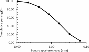
Senaratne S, Lambrousis G, Mirza O, Tam V, Kang W (2017) Recycled concrete in structural applications for sustainable construction practices in Australia. Procedia Eng 180:751–758
Article Google Scholar
Fraj A, Idir R (2017) Concrete based on recycled aggregates - recycling and environmental analysis: a case study of Paris’ region. Constr Build Mater 157:952–964
Adekunle A, Adekunle I, Opafola T, Ogundare I, Adeyeye A (2022) Evaluation of strength characteristics of fibre reinforced concrete: a case study of glass and sisal fibres. Herit Sustainable Dev 4(1):27–31
Gil H, Ortega A, Pérez J (2017) Mechanical behavior of mortar reinforced with sawdust waste. Procedia Eng 200:325–332
Findik F, Findik F (2021) Civil engineering materials. Herit Sustainable Dev 3(2):154–172
Gonzalez J, Jaramillo J, Pérez M, Sablón N, Oliva D (2018) Evaluación físico-mecánicas de tableros a base del Aserrín de Pigüe (Piptocoma discolor) y bagazo de caña de azúcar en Pastaza. Revista Amazónica Ciencia Y Tecnología 7(2):95–104
Escobar S, Trejo D (2019) State of the art of the research on seedling quality of the genus Pinus in Mexico. Revista Mexicana De Ciencias Forestales, 10, 55
Charis G, Danha G, Muzenda E (2019) A review of timber waste utilization: challenges and opportunities in Zimbabwe. Procedia Manuf 35:419–429
Dong Y, Wang K, Li J, Zhang S, Shi S (2020) Environmentally benign wood modifications: a review. ACS Sustainable Chem Eng 8(9):3532–3540
Article CAS Google Scholar
Memon R, Achekzai L, Mohd AS, Abdul A, Memon U (2018) Performance of sawdust concrete at elevated temperature. Jurnal Teknologi 35:419–429
Google Scholar
Mwango A, Kambole C (2019) Engineering characteristics and potential increased utilisation of sawdust composites in construction – a review. J Building Constr Plann Res 7:59–88
James J (2019) Strength benefit of sawdust/wood ash amendment in cement stabilization of an expansive soil. Revista Facultad De Ingenieria 28(50):44–61
Qaidi S, Al-Kamaki Y, Hakeem I, Dulaimi A, Özkılıç Y, Sabri M, Sergeev V (2023) Investigation of the physical-mechanical properties and durability of high-strength concrete with recycled PET as a partial replacement for fine aggregates. Front Mater 10:1101146
De Lima A, Iwakiri S, Satyanarayana K, Lomelí M (2020) Studies on the durability of wood-cement particleboards produced with residues of pinus spp., silica fume, and rice husk ash, BioResources , vol. 15, no. 2, pp. 3064–3086
Meko B, Ighalo J (2021) Utilization of Cordia Africana wood sawdust ash as partial cement replacement in C 25 concrete. Clean Mater, 1
Martínez-García R, Jagadesh P, Zaid O, Șerbănoiu A, Fraile-Fernández F, de Prado-Gil J, Qaidi S, Grădinaru C (2022) The Present State of the Use of Waste Wood Ash as an Eco-Efficient Construction Material: A Review., Materials , vol. 15, p. 5349
Emad W, Ahmed S, Kurda R, Ghafor K, Calaveri L, Qaidi S, Hassan A, Asteris P (2022) Prediction of concrete materials compressive strength using surrogate models. Structures 46:1243–1267
Suliman N, Razak A, Mansor H, Alisibramulisi A, Amin N (2019) Concrete using sawdust as partial replacement of sand: Is it strong and does not endanger health? in MATEC Web of Conferences
Mangi S, Jamaluddin N, Memon S, Ibrahim M (2019) Utilization of sawdust in concrete masonry blocks: a review. Mehran Univ Res J Eng Technol 38(2):487–494
Nayak CB (2021a) Experimental and numerical study on reinforced concrete deep beam in shear with crimped steel fiber. Innovative Infrastructure Solutions 7(1):41
Nayak CB (2020) Experimental and numerical investigation on compressive and flexural behavior of structural steel tubular beams strengthened with AFRP composites. J King Saud Univ - Eng Sci
Suryawanshi N, Nayak C, Gunavant K, Thakare SB (2022) Optimization of self-cured high-strength concrete by Experimental and Grey Taguchi Modelling. Iran J Sci Technol - Trans Civil Eng, 46, 4
García J, Arriola G, Villena L, Muñoz S (2023) Strength of concrete using partial addition of residual Wood Ash with respect to cement | Resistencia Del Concreto Utilizando Adición Parcial De Ceniza De Madera Residual Respecto Al Cemento. Revista Politecnica 52(1):45–54
Nayak CB, Narule GN, Surwase HR (2022) Structural and cracking behaviour of RC T-beams strengthened with BFRP sheets by experimental and analytical investigation. J King Saud Univ - Eng Sci 34(6):398–405
Parlikar A, Naik C, Nayak C (2021) An experimental study on Effect of Pharmaceutical Industrial Waste Water on Compressive Strength of Concrete. Int J Innovative Res Sci Eng Technol 10(8):5
Nayak C, Taware PJU, Jadhav N, Morkhade S (2021b) Effect of SiO2 and ZnO Nano-composites on Mechanical and Chemical properties of modified concrete. Iran J Sci Technol Trans Civil Eng 46:1237–1247
Sales A, Rodriguez de Souza F, Almeida F (2011) Mechanical properties of concrete produced with a composite of water treatment sludge and sawdust. Constr Build Mater 25(6):2793–2798
M.-P. S.P., S.-D. E., B.-C. D. and G.-C. J.M., Use of recycled concrete and rice husk ash for concrete: a review. J Appl Res Technol, 22, pp. 138–155, (2024)
Zanjad N, Pawar S, Nayak C (2022) Use of fly ash cenosphere in the construction Industry: A review, materialstoday: proceedings , vol. 62, no. 4, pp. 2185–2190
Patil L, Nayak CB, Jagadale UT (2022) Effect of copper slag and fly ash and Nano Material to strengthen the properties of concrete. J Emerg Technol Innovative Res, 9, 6
Jagadale U, Jadhav BA, Nayak C (2022) Behaviour of Ternary blended Cement in M40 Grade of concrete. J Emerg Technol Innovative Res (JETIR), 9, 6
Zanjad N, Pawar S, Nayak C (2024) Experimental study on different properties of cenosphere based concrete using calcium lactate, Sigma Journal of Engineering and Natural Sciences , vol. 42, no. 6, pp. XX-XX
Zanjad N, Pawar S, Nayak C (2024) Review on Application of Lightweight Cenosphere in Construction Material, Macromol. Symp , vol. 413, p. 2300006
Disale A, Nayak C, Suryawanshi N, Jadhav N, Jagdale U, Thakare S, Pandey SP, Sharma P, Saxena A, Kate G (2024) Evaluation of Properties of Concrete Without Cement Produced Using Fly Ash-Based Geopolymer, Macromol. Symp , vol. 413, p. 2300003
Kate GK, Nayak CB, Thakare SB (2021c) Optimization of sustainable high-strength–high-volume fly ash concrete with and without steel fiber using Taguchi method and multi-regression analysis. Innovative Infrastructure Solutions 6(2):102
Garcia Chumacero J, Acevedo Torres P, Corcuera La Portilla C, Muñoz Perez S, Villena Zapata L (2023) Effect of the reuse of plastic and metallic fibers on the characteristics of a gravelly soil with clays stabilized with natural hydraulic lime. Innovative Infrastructure Solutions, 8, 185
Muñoz Perez S, Garcia Chumacero J, Charca Mamani S, Villena Zapata L (2023) Influence of the secondary aluminum chip on the physical and mechanical properties of concrete. Innovative Infrastructure Solutions, 45, 8
Muñoz Pérez SP, Santisteban Purizaca JF, Castillo Matute SM, García Chumacero JM, Sánchez Diaz E, Diaz Ortiz EA, Rodriguez ED, Laffite JL (2024) Quispe Osorio and Briceño Mendoza, Glass fiber reinforced concrete: overview of mechanical and microstructural analysis. Innovative Infrastructure Solutions 9(4):116
Bengal SN, Pammar LS, Nayak CB (2022) Engineering application of organic materials with concrete: A review, materialstoday: proceedings , vol. 56, no. 1, pp. 581–586
Bengala SN, Ghodmare S, Nayak CB (2023) PARTIAL REPLACEMENT OF CONCRETE BY STICKY RICE AND JAGGERY. Eur Chem Bull 5:3016–3028
Zanjad N, Pawar S, Nayak C (2024) Self-Healing Molecular Biology for Microbial concrete: a review. Macromol Symp
Bengal SN, Ghodmare S, Nayak CB, Tomar A (2024) Organic admixtures as Additive: an Initiative to reduce Carbon Dioxide Emission due to concrete. Macromol Symp 413:p2300011
Disale A, Nayak C, Suryawanshi N, Jadhav N, Jagdale U, Kate G, Thakare S, Pandey SP, Sharma P, Saxena A (2024) Evaluating Properties of Green Concrete Produced Using Waste Marble Powder, Quarry Dust, and Paper Pulp, Macromol. Symp , vol. 413, p. 2300009
Muñoz S, Villena L, Tesen F, Coronel Y, Garcia J, Brast C (2023) Influence of coconut fiber on mortar properties in masonry walls. Electron J Struct Eng 23(4):52–58
Siddique R, Singh M, Mehta S, Belarbi R (2020) Utilization of treated saw dust in concrete as partial replacement of natural sand. J Clean Prod, 261
Batool F, Islam K, Cakiroglu C, Shahriar A (2021) Effectiveness of wood waste sawdust to produce medium- to low-strength concrete materials. J Building Eng, 44
Ahmed W, Khushnood R, Memon S, Ahmad S, Baloch W, Usman M (2018) Effective use of sawdust for the production of eco-friendly and thermal-energy efficient normal weight and lightweight concretes with tailored fracture properties. J Clean Prod 184(2):1016–1027
Huseien G, Memon R, Kubba Z, Sam A, Asaad M, Mirza J, Memon U (2019) Mechanical, thermal and durable performance of wastes sawdust as coarse aggregate replacement in conventional concrete. Jurnal Teknologi 81(1):151–161
Narayanan A, Hemnath G, Sampaul K, Mary A (2017) Replacement of fine aggregate with sawdust. Int J Adv Res Basic Eng Sci Technol (IJARBEST) 3:206–210
Dias S, Tadeu A, Almeida J, Humbert P, António J, De Brito J, Pinhão P (2022) Physical, Mechanical, and Durability Properties of Concrete Containing Wood Chips and Sawdust: An Experimental Approach, Building , vol. 12, no. 8
Devi K, Lida N, Teyi T, Singh P, Sharma K, Saini N (2023) Utilization of sawdust as sustainable construction material. Lecture Notes Civil Eng 284:137–145
ASTM, C136/C136M (2020) Standard Test Method for Sieve Analysis of Fine and Coarse aggregates. ASTM International, West Conshohocken, PA
ASTM C150 (2007) Standard specification for Portland Cement. ASTM International, West Conshohocken, PA
ASTM, C143/C143M (2020) Standard test method for slump of hydraulic-cement concrete. ASTM International, West Conshohocken, PA
ASTM, C138/138 M (2017) Standard test method for density (Unit Weight), yield, and Air Content (Gravimetric) of concrete. ASTM International, West Conshohocken, PA
ASTM, C231/C231M (2017) Standard test method for air content of freshly mixed concrete by the pressure method. ASTM International, West Conshohocken, PA
ASTM C39 (2021) Standard test method for compressive strength of cylindrical concrete specimens. ASTM International, West Conshohocken, PA
ASTM, C78/C78M (2022) Standard Test Method for Flexural strength of concrete (using simple Beam with Third-Point Loading). ASTM International, West Conshohocken, PA
ASTM, C496/496 M (2017) Standard Test Method for Splitting Tensile Strength of Cylindrical concrete specimens. ASTM International, West Conshohocken, PA
A. C469/C469M, Standard Test Method for Static Modulus of Elasticity and Poisson’s Ratio of Concrete in Compression, West Conshohocken, PA: ASTM International, (2022)
ACI 211.1, Standard practice for selecting proportions for normal, heavy and mass concrete, American Concrete Institute, (2002)
Syafwandi S, Sembodo DS, Munthe AT, Sumarno A (2021) Analysis of the Use of Sawdust Waste as concrete mixture add material against workability and compressive strength concrete with three concrete treatment methods. Int J Eng Sci InformationTechnology (IJESTY), 1, 2
Ugwu J (2019) Saw dust as full replacement of fine aggrgate in lightweight concrete: any comparable strength? Int J Eng Sci (IJES) 8(10):9–11
Fadiel A, Abu-Lebdeh T, Petrescu F (2022) Assessment of woodcrete using destructive and non-destructive test methods, Materials , vol. 15, no. 2
Prasetia I, Putera D, Pratiwi A (2021) Mechanical Performance of Mortar and Concrete Using Borneo Wood Sawdust as Replacement of Fine Aggregate, in The First International Symposium on Civil Engineering and Environmental Research 01/11/–02/11/2021 Online , 2022
Yun C, Rahman M, Huda D, Kuok K, Sze A, Seng J, Bakri M (2022) Sawdust as sand filler replacement in concrete. Waste materials in Advanced sustainable concrete. Springer, pp 133–148
Nurulla S, Mustafa S, Reddy Y (2019) Investigation on mechanical properties of lightweight concrete partially replacing sawdust to fine aggregate. Ann De Chimie: Sci Des Materiaux 43(2):125–128
Maglad A, Mansour W, Fayed S, Tayeh B, Yosri A, Hamad M (2023) Experimental study of the Flexural Behaviour of RC beams made of eco-friendly sawdust concrete and strengthened by a Wooden plate. Int J Concrete Struct Mater, 17, 49
Download references
This study was self-funded by the researchers.
Author information
Authors and affiliations.
Professional School of Civil Engineering, Faculty of Engineering, Architecture and Urbanism, Universidad Señor de Sipan, Chiclayo, 14001, Peru
Geiser Cabanillas Hernandez, Juan Martín García Chumacero, Luis Mariano Villegas Granados, Guillermo Gustavo Arriola Carrasco & Noe Humberto Marín Bardales
You can also search for this author in PubMed Google Scholar
Contributions
Conceptualization: [Cabanillas Hernandez, Geiser], [García Chumacero, Juan Martín]; Methodology: [Cabanillas Hernandez, Geiser], [Villegas Granados, Luis Mariano]; Formal analysis and research: [Cabanillas Hernandez, Geiser], [Arriola Carrasco, Guillermo Gustavo]; Writing - preparation of the original draft: [Cabanillas Hernandez, Geiser], [Villegas Granados, Luis Mariano], [Arriola Carrasco, Guillermo Gustavo]; Writing - revision and editing: [Cabanillas Hernandez, Geiser], [García Chumacero, Juan Martín]; Acquisition of funds: [Cabanillas Hernandez, Geiser]; Resources: [Cabanillas Hernandez, Geiser]; Supervision: [García Chumacero, Juan Martín], [Arriola Carrasco, Guillermo Gustavo], [Marín Bardales, Noe Humberto]. All authors read and approved the final manuscript.
Corresponding author
Correspondence to Juan Martín García Chumacero .
Ethics declarations
Ethical approval.
This study does not contain any studies with human participants and/or animals.
Informed consent
For this type of study a formal consent is not required.
Conflict of interest
The authors declare that they have no known competing financial interests or personal relationships that could have appeared to influence the work reported in this paper.
Additional information
Publisher’s note.
Springer Nature remains neutral with regard to jurisdictional claims in published maps and institutional affiliations.
Rights and permissions
Reprints and permissions
About this article
Cabanillas Hernandez, G., García Chumacero, J.M., Villegas Granados, L.M. et al. Sustainable use of wood sawdust as a replacement for fine aggregate to improve the properties of concrete: a Peruvian case study. Innov. Infrastruct. Solut. 9 , 233 (2024). https://doi.org/10.1007/s41062-024-01567-6
Download citation
Received : 24 January 2024
Accepted : 23 May 2024
Published : 04 June 2024
DOI : https://doi.org/10.1007/s41062-024-01567-6
Share this article
Anyone you share the following link with will be able to read this content:
Sorry, a shareable link is not currently available for this article.
Provided by the Springer Nature SharedIt content-sharing initiative
- Environmental
- Fine aggregate
- Mechanical properties
- Wood sawdust
- Find a journal
- Publish with us
- Track your research
IMAGES
VIDEO
COMMENTS
This case study also demonstrates the five key principles that are integral parts of the incremental commitment model of development: (1) stakeholder satisficing, (2) incremental growth of system definition and stakeholder commitment, (3) iterative system development, (4) concurrent system definition and development, and (5) risk management ...
The primary purpose of this case study is for Systems Analysis and Design, Systems Development, and Database courses. Students examine realistic dialog and Interview Notes, as well as existing documents. For Systems Analysis and Design courses, the students should be able to follow this realistic case study of a small business which arranges ...
For most programming languages an Integrated Development Environment (IDE) can be used to develop the program. An IDE provides a variety of tools for the programmer, and usually includes: Editor. An editor is used for writing the program. Commands are automatically color coded by the IDE to identify command types.
The design for the user interface, database, data inputs and outputs, and reporting are developed here. The result of this phase is a system-design document. This document will have everything a programmer will need to actually create the system. Programming. The code finally gets written in the programming phase.
The primary purpose of this case study is for Systems Analysis and Design, Systems Development, and Database courses. The primary learning objective is for students to integrate the knowledge they have gathered from class discussions and readings, and apply the knowledge to the development of a computer information systems solution for a small ...
this case study begins with the Chief Information Officer (CIO), which might be played by the instructor of the course, who approves and initiates a project and instructs the Project Director to create teams. This new case study is destined to be used in the Advanced Systems Analysis and Development capstone class.
In System Development courses, eg, capstone courses for a computer information systems major, students can use this case study to not only analyze and design a solution, but actually develop the solution using various windows or web-based tools.
Jones M.R., and Nandhakumar J. (1993). Structured development? A structurational analysis of the development of an executive information system, in Human, Organizational, and Social Dimensions of Information Systems Development Arison D., Kendall J.E., and DeGross J.I. (eds) (North-Holland, Amsterdam).
This paper aims at providing a non-trivial practice of integrating the quality control (QC) system into the core ERP processes of a real large-scaled case study.,To satisfy the purpose of the current study, a large-scale steel making holding, inclusive of 27 business units being dispersed over a wide area, has been targeted.
The case study is used to develop some general implications on IS strategy and implementation, which can be taken as themes for debate in any new situation. ... HIRSCHHEIM, R., AND NEWMAN, M. 1991. Symbolism and information systems development: Myth, metaphor and magic Inf. Syst. Res. 2, 1, 29-62. Google Scholar; KEEN, P. 1981. Information ...
A case study approach is used to investigate, in the context of the organisation, how various WWW-based information systems are developed and the reasons why particular strategies are used. The organisations were selected on differences in type, size and information systems developed.
The primary purpose of this case study is for Systems Analysis and Design, Systems Development, and Database courses. Students examine realistic dialog and Interview Notes, as well as existing documents. For Systems Analysis and Design courses, the students should be able to follow this realistic and fairly common case study of a small business ...
It can also be used as a case study in an upper-division or graduate course describing the implementation of the SDLC in practice. INTRODUCTION. The systems development life cycle, in its variant forms, remains one of the oldest and yet still widely used methods of software development and acquisition methods in the information technology (IT ...
This case study articulates all the listed requirements of the modern CIO from vision to risk management to creating high performance teams as part of IT operating model modernization. Furthermore, down the road, there will be sufficient material for a future case study to document the path of the organization to achieving fit-for-purpose data ...
Integration of information systems is a prerequisite for efficient collaboration within and between organizations. Despite intensive research on integration issues in Information Systems research, companies nowadays still encounter considerable challenges in integration projects. The question for the reasons still engages researchers and practitioners. The paper at hand investigates current ...
In System Development courses, e.g., capstone courses for a computer information systems major, students can use this case study to not only analyze and design a solution, but actually develop the solution using various windows or web-based tools. The entire project should require approximately 22-28 hours to complete.
Despite the widespread adoption of Executive Information Systems (EIS) and their increasing importance in organizations, the process of their development is not well understood. The mainstream EIS literature tends to report success stories of EIS in the organizations studied and attribute this to a pre-planned rational process of origin and design of EIS. In this paper, a case study of the EIS ...
Journal of Information Systems Education, Vol. 13(4) 343 A Case Analysis of Real-World Systems Development Experiences of CIS Students Terry L. Fox [email protected] Department of Information Systems, Baylor University Waco, Texas 76798 USA ABSTRACT As effective as an instructor may be, a classroom setting simply cannot offer information ...
The US Office of Management and Budget (OMB) guidance in Circular A-11 [] directs US agencies to develop an AoA for significant investments of resources.The underlying drivers of the AoA in the US and how the AoA should be developed and completed include legislation [], policies [], reviews [], and practice guides [].In both civilian and non-civilian US agencies, the AoA is a standard effort ...
Information systems are critical for companies since they offer quick and easy access to complex and significant data in a structured manner to make informed and effective business decisions. Hence, the objective of this study is to conceptualize and implement an innovative information system in the case study organization. The study identified the requirements for Organizing Vision Theory ...
Information systems design and development revolves around accomplishing a project. A project is a temporary endeavor that provides a solution or fulfills a need in a company. Information systems ...
Strategic Information Systems Planning (SISP) is a critical task that enables organizations to establish crucial IT tools and align a company's strategic plan with reliable IT solutions with the ...
A case study for Information Systems at Zara. Zara is by far the largest, most profitable and most internationalized fashion retail chain. Zara's success is based on a business system that depends on vertical integration, in-house production, quick response, one centralized distribution centre and low advertising cost.
With the rapid development of computer technology, communication technology, and control technology, cyber-physical systems (CPSs) have been widely used and developed. However, there are massive information interactions in CPSs, which lead to an increase in the amount of data transmitted over the network. The data communication, once attacked by the network, will seriously affect the security ...
Currently, wood residues such as sawdust generated by local sawmills are shown as a sustainable alternative to be incorporated in the preparation of concrete. There is a complex environmental problem due to the inadequate management of industrial wastes; therefore, the objective of this study was to evaluate the mechanical properties of concrete using wood sawdust (WS) of the Pinus type ...