Use Case Diagram Tutorial (Guide with Examples)
Use case diagram is a behavioral UML diagram type and frequently used to analyze various systems. They enable you to visualize the different types of roles in a system and how those roles interact with the system. This use case diagram tutorial will cover the following topics and help you create use cases better.

What is a UML Use Case Diagram
Importance of use case diagrams.
- Use Case Diagram Objects
Use Case Diagram Guidelines
Relationships in use case diagrams, identifying actors, identifying use cases.
- When to Use “Include”
- How to Use Generalization
- When to Use “Extend”
- Use Case Diagram Templates of Common Scenarios
A UML (Unified Modeling Language) use case diagram is a visual representation of the interactions between actors (users or external systems) and a system under consideration. It depicts the functionality or behavior of a system from the user’s perspective. Use case diagrams capture the functional requirements of a system and help to identify how different actors interact with the system to achieve specific goals or tasks.
Use case diagrams provide a high-level overview of the system’s functionality, showing the different features or capabilities it offers and how users or external systems interact with it. They serve as a communication tool between stakeholders, helping to clarify and validate requirements, identify system boundaries, and support the development and testing processes.
As mentioned before use case diagrams are used to gather a usage requirement of a system. Depending on your requirement you can use that data in different ways. Below are few ways to use them.
- To identify functions and how roles interact with them – The primary purpose of use case diagrams.
- For a high-level view of the system – Especially useful when presenting to managers or stakeholders. You can highlight the roles that interact with the system and the functionality provided by the system without going deep into inner workings of the system.
- To identify internal and external factors – This might sound simple but in large complex projects a system can be identified as an external role in another use case.
Use Case Diagram objects
Use case diagrams consist of 4 objects.
The objects are further explained below.
Although use case diagrams can be used for various purposes there are some common guidelines you need to follow when drawing use cases.
These include naming standards, directions of arrows, the placing of use cases, usage of system boxes and also proper usage of relationships.
We’ve covered these guidelines in detail in a separate blog post. So go ahead and check out use case diagram guidelines .
There are five types of relationships in a use case diagram. They are
- Association between an actor and a use case
- Generalization of an actor
- Extend relationship between two use cases
- Include relationship between two use cases
- Generalization of a use case
We have covered all these relationships in a separate blog post that has examples with images. We will not go into detail in this post but you can check out relationships in use case diagrams .
How to Create a Use Case Diagram
Up to now, you’ve learned about objects, relationships and guidelines that are critical when drawing use case diagrams. I’ll explain the various processes using a banking system as an example.
- Look for Common Functionality to Reuse
Is it Possible to Generalize Actors and Use Cases
Optional functions or additional functions.
- Validate and Refine the Diagram
Actors are external entities that interact with your system. It can be a person, another system or an organization. In a banking system, the most obvious actor is the customer. Other actors can be bank employee or cashier depending on the role you’re trying to show in the use case.
An example of an external organization can be the tax authority or the central bank. The loan processor is a good example of an external system associated as an actor.
Now it’s time to identify the use cases. A good way to do this is to identify what the actors need from the system. In a banking system, a customer will need to open accounts, deposit and withdraw funds, request check books and similar functions. So all of these can be considered as use cases.
Top level use cases should always provide a complete function required by an actor. You can extend or include use cases depending on the complexity of the system.
Once you identify the actors and the top level use case you have a basic idea of the system. Now you can fine tune it and add extra layers of detail to it.
Look for Common Functionality to Use ‘Include’
Look for common functionality that can be reused across the system. If you find two or more use cases that share common functionality you can extract the common functions and add it to a separate use case. Then you can connect it via the include relationship to show that it’s always called when the original use case is executed. ( see the diagram for an example ).
There may be instances where actors are associated with similar use cases while triggering a few use cases unique only to them. In such instances, you can generalize the actor to show the inheritance of functions. You can do a similar thing for use case as well.
One of the best examples of this is “Make Payment” use case in a payment system. You can further generalize it to “Pay by Credit Card”, “Pay by Cash”, “Pay by Check” etc. All of them have the attributes and the functionality of payment with special scenarios unique to them.
There are some functions that are triggered optionally. In such cases, you can use the extend relationship and attach an extension rule to it. In the below banking system example “Calculate Bonus” is optional and only triggers when a certain condition is matched.
Extend doesn’t always mean it’s optional. Sometimes the use case connected by extending can supplement the base use case. The thing to remember is that the base use case should be able to perform a function on its own even if the extending use case is not called.
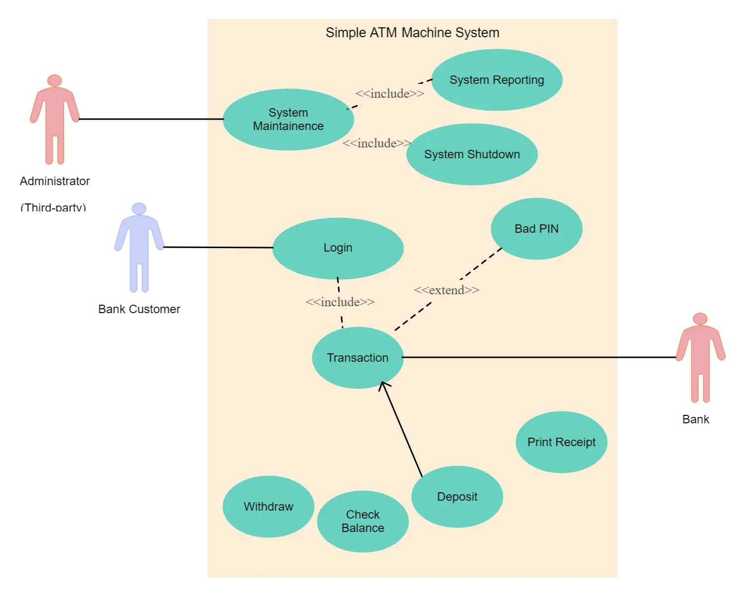
Use Case Diagram Templates
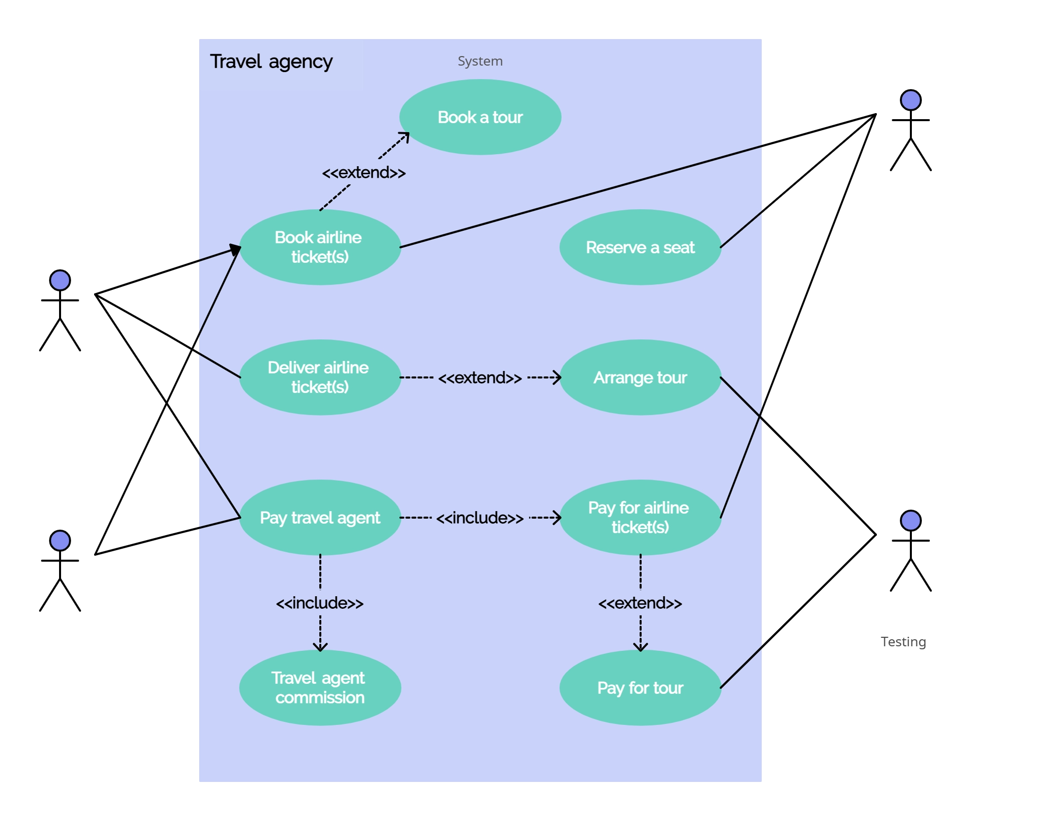
We’ve gone ahead and created use case diagram templates for some common scenarios. Although your problem or scenario won’t be exactly like this you can use them as a starting point. Check out our use case diagram templates .
Questions Regarding the Use Case Diagram Tutorial
We’ve tried to comprehensively cover everything you need to know about creating use case diagrams. If you have doubts about any section or can think of ways to improve this tutorial please let us know in the comments.
More Diagram Tutorials
- Sequence Diagram Tutorial: Complete Guide with Examples
- Business Process Modeling Tutorial (BPM Guide Explaining Features)
- Ultimate Flowchart Guide (Complete Flowchart Tutorial with Examples)
Join over thousands of organizations that use Creately to brainstorm, plan, analyze, and execute their projects successfully.
FAQs on Use Case Diagrams
- Requirement analysis : Use case diagrams aid in understanding and documenting the functional requirements of a system by identifying actors and their interactions.
- System design : Use case diagrams provide a high-level overview of system functionality, helping to define scope and design system components.
- Communication with stakeholders : Use case diagrams facilitate discussions and ensure a shared understanding with stakeholders.
- Project planning and management : Use case diagrams assist in defining scope, prioritizing requirements, and identifying risks.
- Test planning : Use case diagrams help identify scenarios and generate test cases for comprehensive test coverage.
- Documentation : Use case diagrams serve as documentation artifacts for future development, maintenance, and upgrades.
- Identify actors and use cases : Clearly identify the actors, representing external entities interacting with the system, and the use cases, representing system functionalities.
- Use descriptive names : Choose meaningful and descriptive names for actors and use cases to ensure clarity and understanding.
- Define relationships : Establish relationships between actors and use cases to depict their interactions. Use arrows to show the direction of the interaction.
- Keep it simple : Avoid overcomplicating the diagram by focusing on the most essential actors and use cases. Too many details can make the diagram confusing and less effective.
- Use appropriate notation : Follow the standard UML notation for use case diagrams, including ovals for use cases, stick figures for actors, and arrows for relationships.
- Organize and layout : Arrange the actors and use cases in a logical and organized manner, ensuring a clear flow of information. Use lines and connectors to connect related use cases.
- Use hierarchical structure : If the system has complex functionality, consider using a hierarchical structure with primary use cases at the top level and detailed use cases nested beneath.
In a use case diagram, the following elements are typically included:
- Actors: Represent external entities interacting with the system.
- Use cases: Represent specific functionalities or actions performed by the system.
- Relationships: Connect actors and use cases to show interactions and dependencies.
- System boundary: Encloses use cases and actors within the scope of the system.
- Communication paths: Arrows or lines indicating the flow of communication.
On the other hand, use case diagrams do not include the following:
- Internal system details: Focus on high-level functionality, not specific components.
- Sequence of actions: No specific order of execution shown.
- Implementation details: Independent of implementation specifics.
- User interface details: No depiction of visual design or interface elements.
More Related Articles

Software engineer turned tech evangelist. I handle marketing stuff here at Creately including writing blog posts and handling social media accounts. In my spare time, I love to read and travel.
Diagramming Build diagrams of all kinds from flowcharts to floor plans with intuitive tools and templates.
Whiteboarding collaborate with your team on a seamless workspace no matter where they are., data generate diagrams from data and add data to shapes to enhance your existing visuals., enterprise friendly easy to administer and license your entire organization., security see how we keep your data safe., apps & integrations connect to all the tools you use from microsoft, google workspace, atlassian, and more..
- What's New Read about new features and updates.
Product Management Roadmap features, brainstorm, and report on development, so your team can ship features that users love.
Software engineering design and maintain complex systems collaboratively., information technology visualize system architecture, document processes, and communicate internal policies., sales close bigger deals with reproducible processes that lead to successful onboarding and training..
- Getting Started Learn how to make any type of visual with SmartDraw. Familiarize yourself with the UI, choosing templates, managing documents, and more.
- Templates get inspired by browsing examples and templates available in SmartDraw.
Diagrams Learn about all the types of diagrams you can create with SmartDraw.
Whiteboard learn how to combine free-form brainstorming with diagram blueprints all while collaborating with your team., data visualizers learn how to generate visuals like org charts and class diagrams from data., development platform browse built-in data visualizers and see how you can build your own custom visualization., open api the smartdraw api allows you to skip the drawing process and generate diagrams from data automatically., shape data add data to shapes, import data, export manifests, and create data rules to change dashboards that update..
- Explore SmartDraw Check out useful features that will make your life easier.
- Blog Read articles about best practices, find tips on collaborating, learn to give better presentations and more.
Support Search through SmartDraw's knowledge base, view frequently asked questions, or contact our support team.
Site license site licenses start as low as $2,995 for your entire organization..
- Team License The SmartDraw team License puts you in control with powerful administrative features.
Apps & Integrations Connect to all the tools you use.
- Contact Sales
What's New?
Solutions By Team
Save money, reduce hassle, and get more.
Unleash your team's productivity by combining enterprise-class diagramming, whiteboarding, and data while saving 10x over Visio and Lucidchart!
Getting Started Learn to make visuals, familiarize yourself with the UI, choosing templates, managing documents, and more.
Templates get inspired by browsing examples and templates available in smartdraw., developer resources, additional resources.

Team License The SmartDraw Team License puts you in control with powerful administrative features.
Solutions for your team.
Use Case Diagram
Easily visualize your system's functionality with use case diagrams, what is a use case diagram, why make use case diagrams, use case diagram symbols, use case diagram tutorial, use case diagram tips, use case diagram examples, how to make uml diagrams, uml diagram tips, other uml diagrams, with smartdraw, you can create many different types of diagrams, charts, and visuals.
A use case diagram is a dynamic or behavior diagram in UML . Use case diagrams model the functionality of a system using actors and use cases. Use cases are a set of actions, services, and functions that the system needs to perform. In this context, a "system" is something being developed or operated, such as a web site. The "actors" are people or entities operating under defined roles within the system.
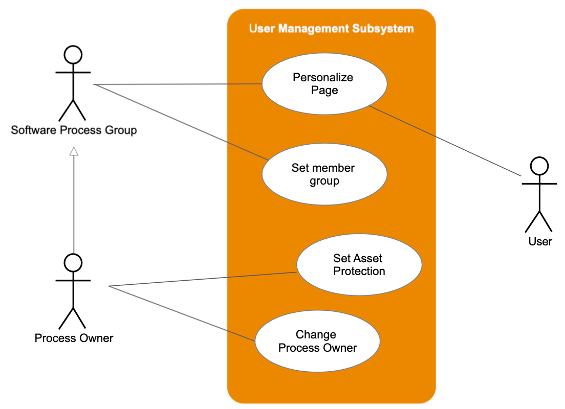
Use case diagrams are valuable for visualizing the functional requirements of a system that will translate into design choices and development priorities.
They also help identify any internal or external factors that may influence the system and should be taken into consideration.
They provide a good high level analysis from outside the system. Use case diagrams specify how the system interacts with actors without worrying about the details of how that functionality is implemented.
Basic Use Case Diagram Symbols and Notations
Draw your system's boundaries using a rectangle that contains use cases. Place actors outside the system's boundaries.

Draw use cases using ovals. Label the ovals with verbs that represent the system's functions.

Actors are the users of a system. When one system is the actor of another system, label the actor system with the actor stereotype.

Relationships
Illustrate relationships between an actor and a use case with a simple line. For relationships among use cases, use arrows labeled either "uses" or "extends." A "uses" relationship indicates that one use case is needed by another in order to perform a task. An "extends" relationship indicates alternative options under a certain use case.

Use Case Diagram Tool Tutorial
Start with one of SmartDraw's blank UML diagram templates or an included use case diagram example. You can quickly add shapes and users and connect them. To add text, just click and type.
Tips for UML Use Case Diagrams
When thinking of use cases, think of the end goal of a user. They don't want to "login" or "sign up." That's not a use case. The use case is more like "make a purchase."
Actors don't have names. They're not "Bob." They represent the role of someone interacting with the system.
Keep your names short and the size of your use cases consistent for a professional look.
For a detailed implementation of a user's goal use a sequence diagram .

Use Case Diagram and Other UML Examples
The best way to understand use case diagrams is to look at some examples of use case diagrams.
Click on any of these UML diagrams included in SmartDraw and edit them:
Browse SmartDraw's entire collection of UML diagram examples and templates
More Use Case Diagram Information
- UML diagram tool
- Software design diagram templates
- Data flow diagram software
- Game design software
Try SmartDraw's Use Case Diagram Software Free
Discover why SmartDraw is the best use case diagram software today.
UML Use Case Diagram: Definition, Application, and Templates
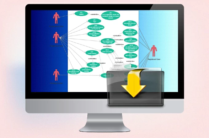
A Use case diagram is part of the Unified modeling language, and is used by developers to see the interaction between the end users of their program and their system. To put more simply, we can say that this type of diagram is the blueprint of the entire interaction between the user and a specific system. There are many elements involved when making this diagram, and that is what we will talk about in the succeeding parts of this post.
UML Use Case Diagram Tutorial
What is use case diagram.
- Use Case Diagram Symbols
- Use Case Diagram Samples and Templates
First of all, let’s get to know what a UML use case diagram is really all about. As mentioned above, the goal of this diagram is to visualize the process of interaction between users and a system. It can change depending on the use case per individual, and provides valuable information to the developers. Using this diagram, they can see if the system is working a it should, or if it needs additional improvements. Additionally, use case diagrams are proven to be effective in explaining complex situations to stakeholders, who don’t have any technical background in software development.
Use case Diagram Symbols
A good diagram is one that doesn’t lack any symbols which can lead to inaccurate data. That is why it is important to familiarize oneself with the different symbols that commonly appear in a specialized diagram like this one. That is why we listed the most common use case diagram symbols that you will encounter when reading one.
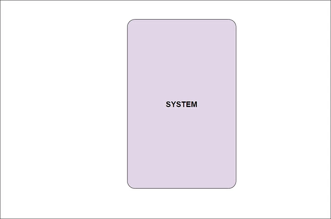
- System Box – This symbol must never disappear from your diagram because it contains the name of the system that you are assessing.
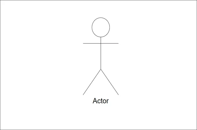
- Actor – This can be represented by a male or female stick figure. It stands for the users who interacts with the system.
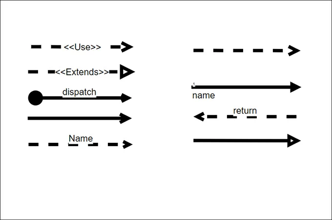
- Relationship – These are lines or arrows that connects the Actors to the System and shows how they are related. This determines the flow of the use case and is key in finding out useful data.
Case Diagram Sample Templates
Using a template is one of the easiest way to execute a UML Use case diagram. This is because it doesn’t involve the actual creation process, and only requires you to fill in the necessary information. On that note, here are some templates that you can immediately use with read-made topics just in case you need them.
Library Management System
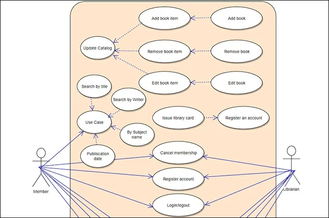
The template above shows the framework between the user and the entire library system. It clearly shows the process and results of each use case just as it should happen in real-life.
Hospital Management System
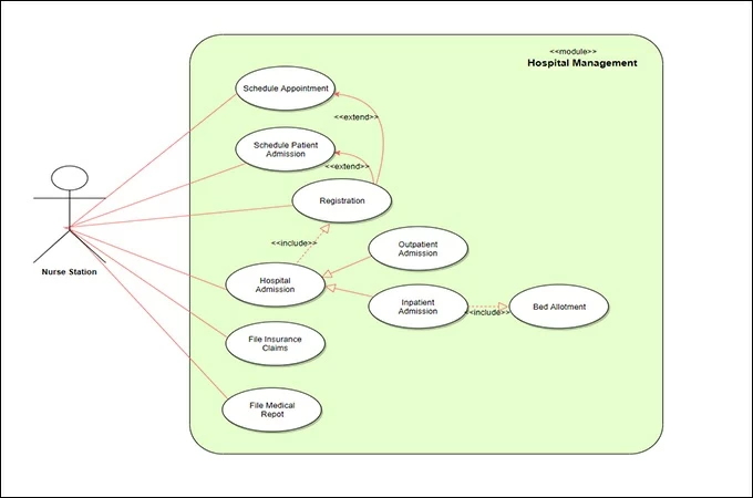
This template uses the Use case diagram symbols to show the hospital management system. The diagram illustrates how the receptionist interacts with various cases and what the succeeding actions should be.
Online Shopping System
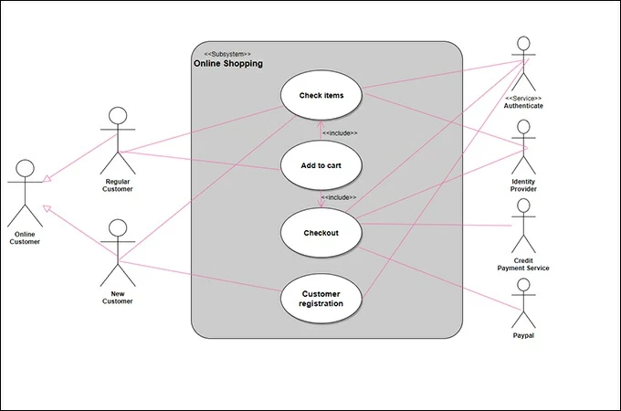
If you are an avid online shopper, then you are aware of the things that you need to do to order something online. This diagram shows exactly what happens when you place an order online, and the process the system follows for you to get your order delivered to your doorstep.
Software Engineering System
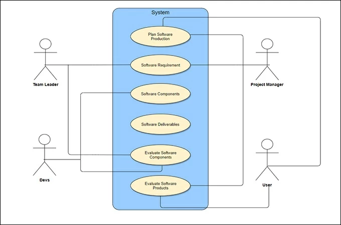
Lastly, we have a slightly complicated diagram since it involves software engineering. There are many variables in software engineering and this is where the use of use case diagram is important. Developers need to test their system if it follows every thing according to the program. That is why they need to use this type of chart, to simplify things for their stakeholders and users.
Starting and maintaining a system needs a solid plan. That is why being prepared for anything that can happen is a prerequisite. On that note, if you are a developer and want to test your system if it follows every protocol, then you need to map out your system. To do so, you’ll need to test it using every possible use case and map it out in a UML use case diagram.
Related posts:
- Top 10 Free Flowchart Maker for Windows and Mac
- Top 10 Free Family Tree Makers in 2024
Leave a Comment
Comment (1).
This website uses cookies that are essential for the operations of this website and its core functions. Other cookies will only be placed with your consent. For more details visit our Cookies Policy .

Create a UML use case diagram
You can create a UML use case diagram in Visio to summarize how users (or actors ) interact with a system, such as a software application. An actor can be a person, an organization, or another system.
Use case diagrams show the expected behavior of the system. They don't show the order in which steps are performed. (Use a sequence diagram to show how objects interact over time .)

Defining the system boundary determines what is considered external or internal to the system.
An actor represents a role played by an outside object. One object may play several roles and, therefore, is represented by several actors.
An association illustrates the participation of the actor in the use case.
A use case is a set of events that occurs when an actor uses a system to complete a process. Normally, a use case is a relatively large process, not an individual step or transaction.
Create a new use case diagram
On the File tab, point to New .
in the Search box, type UML use case .
From the search results, select UML Use Case .
In the dialog box, select the blank template or one of the three starter diagrams. (A description of each one is shown on the right when you select it.) Then select either Metric Units or US Units .
Select Create .
The diagram opens. You should see the Shapes window next to the diagram. A UML Use Case stencil is open in the Shapes window.
(If you don’t see the Shapes window, go to View > Task Panes and make sure that Shapes is selected. If you still don’t see it, click the Expand the Shapes window button on the left.)
Add a subsystem to the use case diagram
Drag a Subsystem shape onto the drawing page. The subsystem can represent your entire system or a major component.

Double-click the Subsystem shape, and then type a new name for the for it, or press the Delete key to delete the existing name. Click outside the shape on the drawing page.
To resize the subsystem, select the shape, and then drag a selection handle.
Add shapes and connectors to the diagram

Use connector shapes to indicate relationships between shapes in the diagram. There are five connectors available:
Example: To indicate a relationship between an actor and a use case
In a use case diagram, drag an Association connector shape onto the drawing page.
Glue one endpoint of the Association shape to a connection point on an Actor shape. Glue the other endpoint to a connection point on a Use Case shape.
For more information about use case diagrams (and procedures for using Microsoft Visual Studio to create use case diagrams), go to UML Use Case Diagrams: Guidelines .
Note: Creating and editing UML diagrams on Visio for the web requires a Visio Plan 1 or Visio Plan 2 license , which is purchased separately from Microsoft 365. For more information, contact your Microsoft 365 admin . If your admin has turned on "self-service purchasing," you can buy a license for Visio yourself. For more details, see Self-service purchase FAQ .
Open Visio for the web .
Near the upper right corner of the page, select More templates .
In the Gallery, scroll down to the UML Use Case row.
The first item in the row represents a blank template plus the companion stencil. The other items in the row are sample diagrams that have some shapes already drawn to help you get started quickly.
Click any item to see a larger preview.
When you find the diagram you want to use, click its Create button.
The new diagram, with the related stencil, opens in your browser.
Visio for the web saves automatically. To rename a drawing, double-click to select the default name (such as Drawing1 ) at the top of the drawing and then type a new name over it.

Need more help?
Want more options.
Explore subscription benefits, browse training courses, learn how to secure your device, and more.

Microsoft 365 subscription benefits

Microsoft 365 training

Microsoft security

Accessibility center
Communities help you ask and answer questions, give feedback, and hear from experts with rich knowledge.

Ask the Microsoft Community

Microsoft Tech Community

Windows Insiders
Microsoft 365 Insiders
Was this information helpful?
Thank you for your feedback.
- System Design Tutorial
- What is System Design
- System Design Life Cycle
- High Level Design HLD
- Low Level Design LLD
- Design Patterns
- UML Diagrams
- System Design Interview Guide
- Crack System Design Round
- System Design Bootcamp
- System Design Interview Questions
- Microservices
- Scalability
Use Case Diagrams | Unified Modeling Language (UML)
- Class Diagram | Unified Modeling Language (UML)
- Unified Modeling Language (UML) Diagrams
- Activity Diagrams | Unified Modeling Language (UML)
- Collaboration Diagrams | Unified Modeling Language(UML)
- Behavioral Diagrams | Unified Modeling Language(UML)
- Object Diagrams | Unified Modeling Language (UML)
- Sequence Diagrams | Unified Modeling Language (UML)
- Class Diagrams vs Object Diagrams | Unified Modeling Language(UML)
- Deployment Diagram in Unified Modeling Language(UML)
- Structural Diagrams | Unified Modeling Language(UML)
- State Machine Diagrams | Unified Modeling Language (UML)
- Conceptual Model of the Unified Modeling Language (UML)
- Which UML Diagrams are mostly used?
- Introduction of Unified Database Language (UDL)
- Use Case Diagram for Library Management System
- Class Diagram for School Management System
- Class diagram for Mall Management system
- Class diagram for Hotel management system
- ER diagram of Bank Management System
A Use Case Diagram is a vital tool in system design, it provides a visual representation of how users interact with a system. It serves as a blueprint for understanding the functional requirements of a system from a user’s perspective, aiding in the communication between stakeholders and guiding the development process.

Important Topics for the Use Case Diagrams
- What is a Use Case Diagram in UML?
- Use Case Diagram Notations
- Use Case Diagram Relationships
- How to draw a Use Case diagram in UML?
- What are common Use Case Diagram Tools and Platforms?
- What are Common Mistakes and Pitfalls while making Use Case Diagram?
- What can be Use Case Diagram Best Practices?
- What are the Purpose and Benefits of Use Case Diagrams?
1. What is a Use Case Diagram in UML?
A Use Case Diagram is a type of Unified Modeling Language (UML) diagram that represents the interaction between actors (users or external systems) and a system under consideration to accomplish specific goals. It provides a high-level view of the system’s functionality by illustrating the various ways users can interact with it.

2. Use Case Diagram Notations
UML notations provide a visual language that enables software developers, designers, and other stakeholders to communicate and document system designs, architectures, and behaviors in a consistent and understandable manner.
1.1. Actors
Actors are external entities that interact with the system. These can include users, other systems, or hardware devices. In the context of a Use Case Diagram, actors initiate use cases and receive the outcomes. Proper identification and understanding of actors are crucial for accurately modeling system behavior.
.webp)
1.2. Use Cases
Use cases are like scenes in the play. They represent specific things your system can do. In the online shopping system, examples of use cases could be “Place Order,” “Track Delivery,” or “Update Product Information”. Use cases are represented by ovals.

1.3. System Boundary
The system boundary is a visual representation of the scope or limits of the system you are modeling. It defines what is inside the system and what is outside. The boundary helps to establish a clear distinction between the elements that are part of the system and those that are external to it. The system boundary is typically represented by a rectangular box that surrounds all the use cases of the system.
Purpose of System Boundary:
- Scope Definition: It clearly outlines the boundaries of the system, indicating which components are internal to the system and which are external actors or entities interacting with the system.
- Focus on Relevance: By delineating the system’s scope, the diagram can focus on illustrating the essential functionalities provided by the system without unnecessary details about external entities.

3. Use Case Diagram Relationships
In a Use Case Diagram, relationships play a crucial role in depicting the interactions between actors and use cases. These relationships provide a comprehensive view of the system’s functionality and its various scenarios. Let’s delve into the key types of relationships and explore examples to illustrate their usage.
3.1. Association Relationship
The Association Relationship represents a communication or interaction between an actor and a use case. It is depicted by a line connecting the actor to the use case. This relationship signifies that the actor is involved in the functionality described by the use case.
Example: Online Banking System
- Actor: Customer
- Use Case: Transfer Funds
- Association: A line connecting the “Customer” actor to the “Transfer Funds” use case, indicating the customer’s involvement in the funds transfer process.
.webp)
3.2. Include Relationship
The Include Relationship indicates that a use case includes the functionality of another use case. It is denoted by a dashed arrow pointing from the including use case to the included use case. This relationship promotes modular and reusable design.
Example: Social Media Posting
- Use Cases: Compose Post, Add Image
- Include Relationship: The “Compose Post” use case includes the functionality of “Add Image.” Therefore, composing a post includes the action of adding an image.

3.3. Extend Relationship
The Extend Relationship illustrates that a use case can be extended by another use case under specific conditions. It is represented by a dashed arrow with the keyword “extend.” This relationship is useful for handling optional or exceptional behavior.
Example: Flight Booking System
- Use Cases: Book Flight, Select Seat
- Extend Relationship: The “Select Seat” use case may extend the “Book Flight” use case when the user wants to choose a specific seat, but it is an optional step.

3.4. Generalization Relationship
The Generalization Relationship establishes an “is-a” connection between two use cases, indicating that one use case is a specialized version of another. It is represented by an arrow pointing from the specialized use case to the general use case.
Example: Vehicle Rental System
- Use Cases: Rent Car, Rent Bike
- Generalization Relationship: Both “Rent Car” and “Rent Bike” are specialized versions of the general use case “Rent Vehicle.”

4. How to draw a Use Case diagram in UML?
Step 1: identify actors.
Determine who or what interacts with the system. These are your actors. They can be users, other systems, or external entities.
Step 2: Identify Use Cases
Identify the main functionalities or actions the system must perform. These are your use cases. Each use case should represent a specific piece of functionality.
Step 3: Connect Actors and Use Cases
Draw lines (associations) between actors and the use cases they are involved in. This represents the interactions between actors and the system.
Step 4: Add System Boundary
Draw a box around the actors and use cases to represent the system boundary. This defines the scope of your system.
Step 5: Define Relationships
If certain use cases are related or if one use case is an extension of another, you can indicate these relationships with appropriate notations.
Step 6: Review and Refine
Step back and review your diagram. Ensure that it accurately represents the interactions and relationships in your system. Refine as needed.
Step 7: Validate
Share your use case diagram with stakeholders and gather feedback. Ensure that it aligns with their understanding of the system’s functionality.
Let’s understand how to draw a Use Case diagram with the help of an Online Shopping System:
2. use cases:.
- Browse Products
- Add to Cart
- Manage Inventory (Admin)
3. Relations:
- The Customer can browse products, add to the cart, and complete the checkout.
- The Admin can manage the inventory.
Below is the usecase diagram of an Online Shopping System:

5. What are common Use Case Diagram Tools and Platforms?
Several tools and platforms are available to create and design Use Case Diagrams. These tools offer features that simplify the diagram creation process, facilitate collaboration among team members, and enhance overall efficiency. Here are some popular Use Case Diagram tools and platforms:
6.1. Lucidchart
- Cloud-based collaborative platform.
- Intuitive drag-and-drop interface.
- Real-time collaboration and commenting.
- Templates for various diagram types.
- Integration with other tools like Jira and Confluence.
6.2. draw.io
- Free, open-source diagramming tool.
- Works offline and can be integrated with Google Drive, Dropbox, and others.
- Offers a wide range of diagram types, including Use Case Diagrams.
- Customizable shapes and themes.
6.3. Microsoft Visio
- Part of the Microsoft Office suite.
- Supports various diagram types, including Use Case Diagrams.
- Integration with Microsoft 365 for collaborative editing.
- Extensive shape libraries and templates.
6.4. SmartDraw
- User-friendly diagramming tool.
- Templates for different types of diagrams, including Use Case Diagrams.
- Integration with Microsoft Office and Google Workspace.
- Auto-formatting and alignment features.
6.5. PlantUML
- Open-source tool for creating UML diagrams.
- Text-based syntax for diagram specification.
- Integrates with various text editors and IDEs.
- Supports collaborative work using version control systems.
6. What are Common Mistakes and Pitfalls while making Use Case Diagram?
Avoiding common mistakes ensures the accuracy and effectiveness of the Use Case Diagram. Here are key points for each mistake:
6.1. Overcomplication:
- Mistake: Including excessive detail in the diagram.
- Impact: Confuses stakeholders and complicates understanding.
- Prevention: Focus on essential use cases and maintain an appropriate level of abstraction.
6.3. Ambiguous Relationships:
- Mistake: Unclear relationships between actors and use cases.
- Impact: Causes misinterpretation of system interactions.
- Prevention: Clearly define and label relationships with proper notation.
6.3. Inconsistent Naming Conventions:
- Mistake: Inconsistent naming of actors and use cases.
- Impact: Causes confusion and hinders communication.
- Prevention: Establish and adhere to a consistent naming convention.
6.4. Misuse of Generalization:
- Mistake: Incorrect use of generalization relationships.
- Impact: Misrepresentation of the “is-a” relationship between use cases or actors.
- Prevention: Ensure accurate usage to represent specialization relationships.
6.5. Overlooking System Boundaries:
- Mistake: Not clearly defining the system boundary.
- Impact: Challenges understanding of the system’s scope.
- Prevention: Clearly enclose relevant actors and use cases within a system boundary.
6.6. Lack of Iteration:
- Mistake: Treating the diagram as a static artifact.
- Impact: May become outdated and not reflect the current state of the system.
- Prevention: Use an iterative approach, updating the diagram as the system evolves.
7. What can be Use Case Diagram Best Practices?
Creating effective and clear Use Case Diagrams is crucial for communicating system functionality and interactions. Here are some best practices to follow:
7.1 Keep it Simple:
- Focus on High-Level Functionality: Avoid unnecessary details and concentrate on representing the system’s primary functionalities.
- Use Concise Language: Use clear and concise language for use case and actor names to enhance readability.
7.2 Consistency:
- Naming Conventions: Maintain a consistent naming convention for use cases and actors throughout the diagram. This promotes clarity and avoids confusion.
- Formatting Consistency: Keep a consistent format for elements like ovals (use cases), stick figures (actors), and lines to maintain a professional look.
7.3. Organize and Align:
- Logical Grouping: Organize use cases into logical groups to represent different modules or subsystems within the system.
- Alignment: Maintain proper alignment of elements to make the diagram visually appealing and easy to follow.
7.4. Use Proper Notation:
- Consistent Symbols: Adhere to standard symbols for actors (stick figures), use cases (ovals), and relationships to ensure understanding.
- Proper Line Types: Clearly distinguish between association, include, extend, and generalization relationships using appropriate line types.
7.5. Review and Iterate:
- Feedback Loop: Regularly review the diagram with stakeholders to ensure accuracy and completeness.
- Iterative Process: Use an iterative process, updating the diagram as the system evolves or more information becomes available.
By following these best practices, you can create Use Case Diagrams that effectively communicate the essential aspects of a system, fostering a shared understanding among stakeholders and facilitating the development process.
8. What are the Purpose and Benefits of Use Case Diagrams?
The Use Case Diagram offers numerous benefits throughout the system development process. Here are some key advantages of using Use Case Diagrams:
- Use Case Diagrams provide a visual representation of the system’s functionalities and interactions with external entities.
- This visualization helps stakeholders, including non-technical ones, to understand the system’s high-level behavior.
- Use Case Diagrams serve as a powerful communication tool, facilitating discussions between stakeholders, developers, and designers.
- They provide a common language for discussing system requirements, ensuring a shared understanding among diverse team members.
- During the requirements analysis phase, Use Case Diagrams help in identifying, clarifying, and documenting user requirements.
- They capture the various ways users interact with the system, aiding in a comprehensive understanding of system functionality.
- Use Case Diagrams center around user goals and scenarios, emphasizing the perspective of external entities (actors).
- This focus on user interactions ensures that the system is designed to meet user needs and expectations.
- In the system design phase, Use Case Diagrams aid in designing how users (actors) will interact with the system.
- They contribute to the planning of the user interface and help in organizing system functionalities.
- Use Case Diagrams are valuable for deriving test cases and validating system behavior.
- Testers can use the diagrams to ensure that all possible scenarios, including alternative and exceptional paths, are considered during testing.
9. Conclusion
In conclusion, a Use Case Diagram in UML serves as a powerful tool for capturing and visualizing the functional requirements and interactions within a system. By representing actors, use cases, and their relationships in a clear and concise manner, this diagram provides a high-level overview of the system’s behavior.
Please Login to comment...
Similar reads.
- Geeks Premier League 2023
- Geeks Premier League
- System Design
Improve your Coding Skills with Practice

What kind of Experience do you want to share?
We use essential cookies to make Venngage work. By clicking “Accept All Cookies”, you agree to the storing of cookies on your device to enhance site navigation, analyze site usage, and assist in our marketing efforts.
Manage Cookies
Cookies and similar technologies collect certain information about how you’re using our website. Some of them are essential, and without them you wouldn’t be able to use Venngage. But others are optional, and you get to choose whether we use them or not.
Strictly Necessary Cookies
These cookies are always on, as they’re essential for making Venngage work, and making it safe. Without these cookies, services you’ve asked for can’t be provided.
Show cookie providers
- Google Login
Functionality Cookies
These cookies help us provide enhanced functionality and personalisation, and remember your settings. They may be set by us or by third party providers.
Performance Cookies
These cookies help us analyze how many people are using Venngage, where they come from and how they're using it. If you opt out of these cookies, we can’t get feedback to make Venngage better for you and all our users.
- Google Analytics
Targeting Cookies
These cookies are set by our advertising partners to track your activity and show you relevant Venngage ads on other sites as you browse the internet.
- Google Tag Manager
- Infographics
- Daily Infographics
- Popular Templates
- Accessibility
- Graphic Design
- Graphs and Charts
- Data Visualization
- Human Resources
- Beginner Guides
Blog Graphic Design 10 Use Case Diagram Examples (and How to Create Them)
10 Use Case Diagram Examples (and How to Create Them)
Written by: Letícia Fonseca Feb 15, 2022
Use case diagrams are a great tool that can help businesses and developers alike to design processes and systems.
By capturing requirements and expectations from a user’s point of view, they ensure the development of correct and efficient systems that will properly serve a user’s goals.
In this article, we will define what a use case diagram is and provide you with different use case diagram examples.
You can create your own use case diagrams using Venngage’s Diagram Maker and use case diagram templates . No design experience is required!
Click to jump ahead:
What is a use case diagram?
- 5 Use case diagram examples and templates that you can use
What are the benefits of a use case diagram?
Types of use case diagrams, what are the elements of a uml use case diagram, faqs about use case diagrams.
A use case diagram is a visual representation of the different ways and possible scenarios of using a system. It illustrates how a user will perform actions and interact with a particular system, such as a website or an app.
For example, this use case diagram depicts the different functions of a banking system for customers:

In Unified Modeling Language (UML), systems are presented at different levels of detail to show a specific perspective in the system’s design. Use case diagrams are considered UML diagrams.
UML diagrams define and organize the high-level functions and scope of a system. By modeling the basic flow of events in a use case, they help identify the goals that you need to achieve with every system-user interaction.
5 Use case diagram examples and templates that you can use:
Here are some use case diagram templates and examples to guide your diagram creation process:
Retail use case diagram
This use case diagram example depicts the internal functions and employee interactions within a retail system.

It features basic system functions represented by color-coordinated boxes to signify use cases based on the user’s role. A use case diagram like this can be of great use to retail stores with B2C e-commerce systems.
Design a use case or UML diagram that reflects your brand with Venngage’s My Brand Kit feature.
Add your website when prompted and the editor automatically imports all your brand assets, including your logo, colors, and fonts.
Restaurant use case diagram
In this example, a restaurant’s daily operations serve as the system, the staff represent the actors, and their tasks are the use cases.
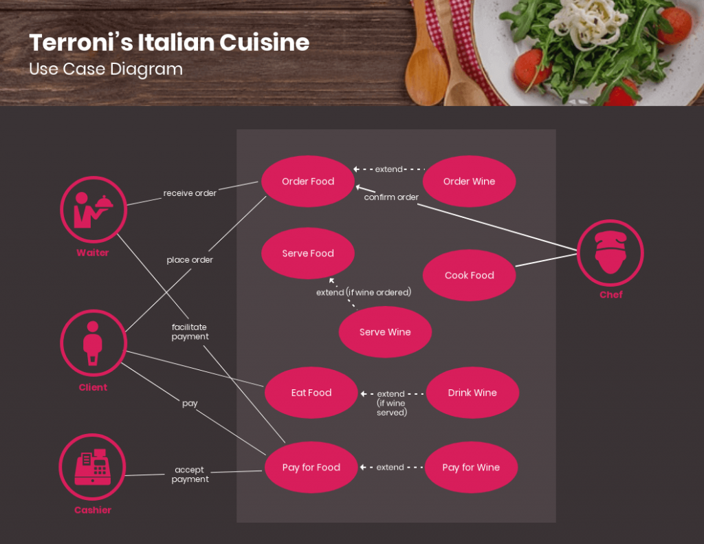
This use case diagram can be particularly helpful to restaurants or fast-food chains in terms of systemizing routine processes and presenting day-to-day activities to employees in a simpler and more orderly way.
Travel use case diagram
Here is a use case diagram that maps out how different types of users can engage with a travel booking website or application.

This comprehensive template includes extended use cases marked by dotted lines and arrows instead of simple lines. It can be scaled down or up for hotels, airlines, and other travel reservation systems.
Banking use case diagram
Designed for automated teller machine (ATM) systems, this use case diagram portrays different types of transactions as use cases.

As this example is very simple and contains only essential elements, it can be adapted for other banking systems like branch banking or online banking.
Consumer electronics store use case diagram
Last but not least, this use case diagram example illustrates how sales and management teams can use a retail system to carry out tasks.
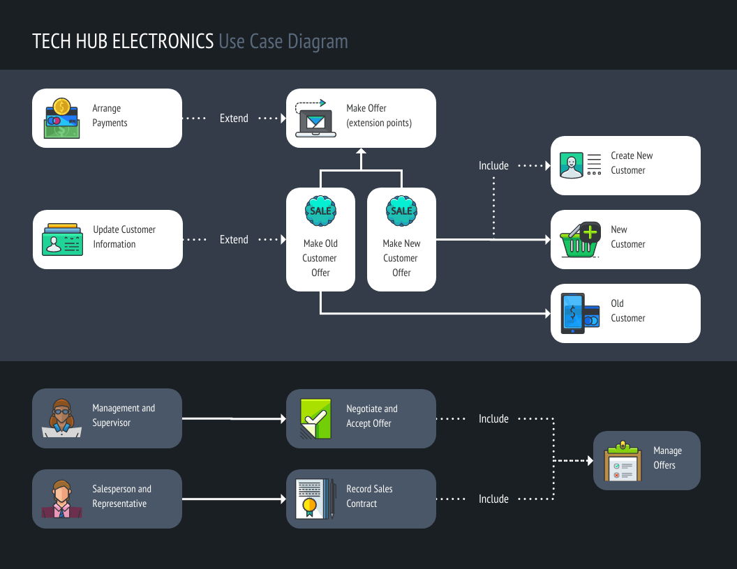
It can be applied to retail systems for consumer electronics and home appliances, fast-moving consumer goods, and other retail sectors.
Ready to master use case diagrams? Check out our blog for everything you need to know and more use case diagram examples for your inspiration.
Use case diagrams can aid your development process with the following benefits:
- Guiding development: Use case diagrams can help establish the cost and complexity of your system. It does so by specifying which functions become requirements that will make it to the development stage.
- User-driven approach: Use case diagrams are written in natural language, which helps users easily understand them. Additionally, they provide businesses an excellent way to communicate with customers. Here is a use case diagram example that shows the basic transactional path of a banking customer:

- Simplifying solutions: By breaking down solutions into practical functions or features, use case diagrams can decrease the complexity of the problem that your system is trying to solve.
- Tracking progress: Use case diagrams can be used to monitor which use cases have been implemented, tested, and delivered and help you identify which functions work and which ones don’t.
Create use case diagrams that are easy to understand with Venngage’s extensive icon library. We offer 40,000+ icons, including diverse people icons, so your diagrams can reflect your users more accurately.
Double-click an icon in your chosen template, and choose from the options in the menu.
There are many different types of diagrams that can be used for designing and representing systems and processes. As for UML use case diagrams, they are classified into two types: behavioral and structural UML diagrams.
Behavioral UML diagrams
Behavioral UML diagrams provide a standard way to visualize the design and behavior of a system. Under them are 7 other types of diagrams which are:
- Activity diagrams
- State machine diagrams
- Sequence diagrams
- Communication diagrams
- Interaction overview diagrams
- Timing diagrams
- Use case diagrams
As an example, this use case diagram portrays how an ATM system will behave or react when a customer or administrator performs an action.

Structural UML diagrams
Structural UML diagrams on the other hand focus on depicting the concepts involved in a system and how they relate to each other. There are also 7 types of structural UML diagrams:
- Class Diagram
- Component Diagram
- Deployment Diagram
- Object Diagram
- Package Diagram
- Profile Diagram
- Composite Structure Diagram
Use case diagrams contain a combination of different elements and specialized symbols and connectors. Whether you want your use case diagram to be simple or in-depth, it should include the following basic components:
- Actors – An actor is anyone who performs an action using your system. Actors or users can be a person, an organization, or an external system. Actors are represented by stick figures in a use case diagram. In this example, the functions of a system are modeled for two types of actors: persons and organizations.

- System – The system scope covers a sequence of actions and interactions between users and the system. To depict the system boundary, system boundary boxes are used to signify that a use case is within the scope of the system.
- Use cases – Use cases are the different uses or applications that your system can offer users. Horizontally shaped ovals are used to symbolize use cases while lines are drawn to connect the user to the use case. Here is an example to illustrate the relationship between users and use cases:

- Goals – The goal is the end result of a use case. An effective use case diagram should describe the activities involved in reaching the goals behind each use case.
What is included and not included in a use case diagram?
Use case diagrams describe the relationship between the users, the system, and its use cases. They do not need to go into a lot of detail and explain how the system operates internally. Here is a guide on what to include and what not to include in your use case diagram:
What to include:
- Who is using the system
- How the user will use the system
- What the user’s goal is
- What steps the user takes to accomplish a task
- How the system responds to a particular action
What not to include:
- The order in which steps are performed
- Details about user interfaces
- Programming language
When to apply use case diagrams
Here are some situations where applying use case diagrams can be particularly useful:
Early stages of system development:
- Gather and visualize requirements: Capture the needs and goals of different user groups and how the system interacts with them.
- Define system scope: Ensure you’re building the right features and functions based on user needs.
- Identify potential issues: Spot inconsistencies or missing functionalities early on in the development process.
Communication and collaboration:
- Explain system functionality to stakeholders: Offer a clear and concise visual representation of what the system does and how it works.
- Facilitate discussions and feedback: Use the diagram as a starting point for discussions and encourage user input into the design process.
- Align teams on system goals: Ensure everyone involved has a shared understanding of the user experience and system objectives.
Testing and documentation:
- Derive test cases: Use the diagram to identify different use cases and scenarios to test the system functionality.
- Document system behavior: Provide a clear and easily understandable reference for future maintenance and updates.
- Support ongoing communication: Explain complex system features to new team members or users.
Beyond these situations, consider using use case diagrams when:
- You want to focus on the “what” and “why” instead of the technical details.
- You need to deal with multiple user types with different needs and functionalities.
- You want to increase understanding and agreement among stakeholders.
How do you write a use case diagram?
Writing a use case diagram involves deconstructing processes in order to reveal a basic overview of your system. Here are some steps that you can follow:
Step 1: Identify the actors (users) who are going to be engaging with your system. Categorize each type of user based on their roles.
Step 2: Pick one type of user and list what actions they would take using the system. Each action becomes a use case.
Step 3: Create a goal for every use case. Identify what is required from the system to achieve these goals.
Step 4: Structure the use cases. Include in the description for each use case the basic course of events that will happen when a user performs a certain action. It should describe what the user does and how the system responds.
Step 5: Take into consideration alternate courses of events and add them to extend the use case.
Step 6: Repeat steps 2-5 to create a use case diagram for each type of user.
What software is used to create a use case diagram?
There are various tools and software available for creating a use case diagram. For starters, you can try Microsoft Visio which is a diagramming and vector graphics application that is part of the Microsoft Office family.
You can also go for web-based software if you don’t want the hassle of downloading, installing, and updating programs. Venngage’s diagram features include pre-made use case diagram templates that you can customize for your business and development needs.
Don’t guess, visualize: Use case diagrams map how you gain from this system
Creating a use case diagram can help you illustrate how your system can fulfill the needs and goals of your users. Make sure to use Venngage’s diagram maker to create a successful use case diagram for your next project.
Discover popular designs

Infographic maker

Brochure maker

White paper online

Newsletter creator
Flyer maker
Timeline maker

Letterhead maker
Mind map maker

Ebook maker

UML Use Case Diagram Examples
What are your diagramming needs.
Lucidchart is a diagramming solution for UML with deep integration with third-party apps. Make the diagram itself in Lucidchart, and create your use case scenario document with a program like Google Docs!
3 minute read
Want to make a Diagram of your own? Try Lucidchart. It's quick, easy, and completely free.
What is a use case diagram in UML?
Outline your use case diagram.
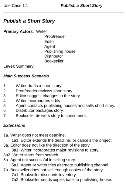
Use case scenario documents break down a process by describing the actors, the typical workflow, and the things that could go wrong, called extensions. When managing projects that use UML conventions, there can be a temptation to jump straight into the use case diagram, with stick figures, ovals, and lots of lines. But if you don’t know your goals and who’s involved, take a step back and write your goals down in prose. Alistair Cockburn is a leader in designing use case scenarios; visit his website to get inspired!
This is a brief example the process of withdrawing money from an ATM. The outline goes through each of the steps that are likely to occur in the process, including each of the errors that could likely occur. Outlining the process like this will help you to outline the process, making the act of diagramming your use case scenario easier than ever.
Diagramming is quick and easy with Lucidchart. Start a free trial today to start creating and collaborating.
Use case diagram examples in Lucidchart
Book publishing use case diagram example.
This use case diagram is a visual representation of the prose scenario shown above. Whether you’re an author, an agent, or a bookseller, inserting this diagram into your use case scenario can help your team publish the next big hit. Try our demo template for a book publishing use case diagram here.

Railway reservation use case diagram example
This customizable template can be adapted for any process where a customer is purchasing a service. With attractive color schemes, text that’s easy to read and edit, and a wide-ranging UML shape library, you’re ready to go! Jump right in and try our demo template to get started.
Banking system use case diagram example
Modern banking systems need to have clear objectives. This diagram presents a high-level overview of some of the most fundamental goals a customer has with his or her bank—opening an account, checking a balance, and withdrawing money. If you like this template try it out in Lucidchart for a banking system use case diagram here.
How to make a use case diagram
In Lucidchart, creating a use case diagram from scratch is surprisingly simple.
Create a use case scenario document to organize the process and all possible alternative extensions.
Open a blank Lucidchart document or start with a template and enable the UML shape library.
Select the shape you want and drag out symbols from the toolbox to the canvas
Then model the process flow by drawing lines between shapes while adding text.
Dive deeper into this guide on how to draw a use case diagram in UML for additional insight. It's easy to resize and style any element. You can even import SVG shapes and Visio files for a custom solution. If you'd like to learn more about UML, check out our What is UML tutorial.
Additional Resources
- What is an BPMN and how to create one
- How to Make a Synoptic Table in Excel
- How to Make a Synoptic Chart in PowerPoint
- How to Make a Synoptic Table in Word
- Examples and Templates for Synoptic Tables
- What is and how to create an ERD
- What is an process map and how to create one
- What is a Data Flow Diagram (DFD) and How to Create One
- How to Make a Synoptic Table
- PowerPoint Flowchart Template Guide
- What is an Value Stream Map (VSM) and how to create one
- Workflow diagram tutorial
- What is a Swimlane Diagram and Steps to Create One
- What is an Network Diagram and how to create one
- What is and how to create a decision tree
- P&ID Examples
- How to Draw a Use Case Diagram in UML
Lucidchart is a flexible tool for building use case scenarios in prose or in diagrams. There’s no need to install expensive, slow software when you can edit, perfect, and publish your use case scenarios and diagrams from your browser!

UML Use Case Diagram: Tutorial with EXAMPLE
What is the Use Case Diagram?
Use Case Diagram captures the system’s functionality and requirements by using actors and use cases. Use Cases model the services, tasks, function that a system needs to perform. Use cases represent high-level functionalities and how a user will handle the system. Use-cases are the core concepts of Unified Modelling language modeling.
Why Use-Case diagram?
A Use Case consists of use cases, persons, or various things that are invoking the features called as actors and the elements that are responsible for implementing the use cases. Use case diagrams capture the dynamic behaviour of a live system. It models how an external entity interacts with the system to make it work. Use case diagrams are responsible for visualizing the external things that interact with the part of the system.
Use-case diagram notations
Following are the common notations used in a use case diagram:
Use cases are used to represent high-level functionalities and how the user will handle the system. A use case represents a distinct functionality of a system, a component, a package, or a class. It is denoted by an oval shape with the name of a use case written inside the oval shape. The notation of a use case in UML is given below:

It is used inside use case diagrams. The actor is an entity that interacts with the system. A user is the best example of an actor. An actor is an entity that initiates the use case from outside the scope of a use case. It can be any element that can trigger an interaction with the use case. One actor can be associated with multiple use cases in the system. The actor notation in UML is given below.

How to draw a use-case diagram?
To draw a use case diagram in UML first one need to analyse the entire system carefully. You have to find out every single function that is provided by the system. After all the functionalities of a system are found out, then these functionalities are converted into various use cases which will be used in the use case diagram.
A use case is nothing but a core functionality of any working system. After organizing the use cases, we have to enlist the various actors or things that are going to interact with the system. These actors are responsible for invoking the functionality of a system. Actors can be a person or a thing. It can also be a private entity of a system. These actors must be relevant to the functionality or a system they are interacting with.
After the actors and use cases are enlisted, then you have to explore the relationship of a particular actor with the use case or a system. One must identify the total number of ways an actor could interact with the system. A single actor can interact with multiple use cases at the same time, or it can interact with numerous use cases simultaneously.
Following rules must be followed while drawing use-case for any system:
- The name of an actor or a use case must be meaningful and relevant to the system.
- Interaction of an actor with the use case must be defined clearly and in an understandable way.
- Annotations must be used wherever they are required.
- If a use case or an actor has multiple relationships, then only significant interactions must be displayed.
Tips for drawing a use-case diagram
- A use case diagram should be as simple as possible.
- A use case diagram should be complete.
- A use case diagram should represent all interactions with the use case.
- If there are too many use cases or actors, then only the essential use cases should be represented.
- A use case diagram should describe at least a single module of a system.
- If the use case diagram is large, then it should be generalized.
An example of a use-case diagram
Following use case diagram represents the working of the student management system:

In the above use case diagram, there are two actors named student and a teacher. There are a total of five use cases that represent the specific functionality of a student management system. Each actor interacts with a particular use case. A student actor can check attendance, timetable as well as test marks on the application or a system. This actor can perform only these interactions with the system even though other use cases are remaining in the system.
It is not necessary that each actor should interact with all the use cases, but it can happen.
The second actor named teacher can interact with all the functionalities or use cases of the system. This actor can also update the attendance of a student and marks of the student. These interactions of both student and a teacher actor together sums up the entire student management application.
When to use a use-case diagram?
A use case is a unique functionality of a system which is accomplished by a user. A purpose of use case diagram is to capture core functionalities of a system and visualize the interactions of various things called as actors with the use case. This is the general use of a use case diagram.
The use case diagrams represent the core parts of a system and the workflow between them. In use case, implementation details are hidden from the external use only the event flow is represented.
With the help of use case diagrams, we can find out pre and post conditions after the interaction with the actor. These conditions can be determined using various test cases.
In general use case diagrams are used for:
- Analyzing the requirements of a system
- High-level visual software designing
- Capturing the functionalities of a system
- Modeling the basic idea behind the system
- Forward and reverse engineering of a system using various test cases.
Use cases are intended to convey desired functionality so the exact scope of a use case may vary according to the system and the purpose of creating UML model.
- Use case diagrams are a way to capture the system’s functionality and requirements in UML diagrams .
- It captures the dynamic behavior of a live system.
- A use case diagram consists of a use case and an actor.
- A use case represents a distinct functionality of a system, a component, a package, or a class.
- An actor is an entity that initiates the use case from outside the scope of a use case.
- A purpose of use case diagram is to capture the core functionalities of a system.
- State Machine Diagram & Statechart Diagram in UML
- UML Relationships Types: Association, Dependency, Generalization
- UML Association Vs. Aggregation Vs. Composition [EXAMPLE]
- Interaction, Collaboration & Sequence Diagrams with Examples
- UML Tutorial PDF for Beginners
- 13 Best FREE Microsoft Visio Alternatives & Competitors (2024)
- UML Diagram Cheat Sheet and Reference Guide
- Difference Between Aggregation and Composition in UML
- Start diagramming Start diagramming
Figma design
Design and prototype in one place
Collaborate with a digital whiteboard

Translate designs into code
Get the desktop, mobile, and font installer apps
See the latest features and releases
- Prototyping
- Design systems
- Wireframing
- Online whiteboard
- Team meetings
- Strategic planning
- Brainstorming
- Diagramming
- Product development
- Web development
- Design handoff
- Product managers
Organizations
Config 2024
Register to attend in person or online — June 26–27

Creator fund
Build and sell what you love
User groups
Join a local Friends of Figma group
Learn best practices at virtual events
Customer stories
Read about leading product teams
Stories about bringing new ideas to life
Get started
- Developer docs
- Best practices
- Reports & insights
- Resource library
- Help center
FigJam Visualize user experiences with a use case template
Examine your systems from the user’s perspective so you can understand them inside and out. FigJam’s simple use case templates will give your team the tools to investigate user journeys from beginning to end.

Use case template
Take team members through specific user scenarios step by step from anywhere in the world.
A breakdown worth getting behind
Translate user intentions and pathways into actionable goals that everyone on your team (developer or not) can rally around.
Get to know it: Use case diagrams make concepts easy to understand, no matter your level of technical know-how.
Get ahead of it: Notice potential roadblocks ahead of time, and avoid them with ease.
Take it with you: Enter the next phase of development with clarity and confidence.

FigJam Brainstorm with the best of them
Your team is your most precious resource. Analyze and render use cases together without the hassle—FigJam templates are full-blown digital meeting spaces, complete with easy-to-use tools and widgets like sticky notes, polls, and comment boxes that make feedback fun.
Follow the dotted line
Plot a path for your team to follow. FigJam’s intuitive, interactive workflow templates take the pain out of planning.

Work plan template
Visualize a bright future, then build a road toward it.
Agile roadmap template
Stay on your toes through short cycle flows.
Other templates from the community
Collaborate easily with your fellow travelers.
How to make a use case diagram?
Start by downloading FigJam’s simple use case template, which will function as your blank canvas. Then, identify who will be using your product or application and the various use cases that they may participate in. But what does “use case” mean, anyway? Simply put, it’s a potential scenario that depicts how someone might interact with a product or experience, including events like “add to cart” and “checkout” or “enters bar,” “orders drink,” and “pays tab.”
Speaking of these events, this is what you’ll add to your use case diagram template next, as well as system-user functions and connections between the various actors, use cases, and functions.
Why use use case diagram?
Use case diagrams provide valuable information about how and why users are interacting with a system. This can help development teams focus resources and prioritize tasks, and also pinpoint possible problem areas ahead of time.
What is a use case example used for? Here’s an instance of where they would have come in handy:
A user logs on to a website to buy replacement filters for an air purifier. They navigate to the product page for their purifier model. They locate the information about the filter, but the filter’s product page isn’t linked to the purifier product page. Because of this, the user Googles the filter information and ends up buying generic replacement filters from a different company.
Use case diagrams help companies avoid scenarios like this by considering the experience from the perspective of the user seeking out replacement filters.
When creating a use case diagram, what is the first step?
The first and most important step of creating a use case diagram is determining which user point-of-view you’ll be diagramming. Start by establishing an understanding of the typical users of your system, and the reasons why they’re interacting with the system in the first place—what they need, want, like, and respond to. Then narrow the scope to a specific system interaction and begin diagramming.
Other templates you might like

Explore 1,000+ templates on the Figma community
Explore even more templates, widgets, and plugins—all built by the Figma community.

Home » Use Case Analysis » Creating Sequence Diagrams with a Use Case-Driven Approach: A Comprehensive Guide
Creating Sequence Diagrams with a Use Case-Driven Approach: A Comprehensive Guide
- Posted on March 21, 2023
- / Under Use Case Analysis , Visual Modeling
What is a Sequence Diagram
Software development requires an efficient communication and understanding between all stakeholders involved in the project. One of the essential tools for effective communication and understanding is the sequence diagram. A sequence diagram is a graphical representation of the interactions between different components of a system over time. To create a sequence diagram that accurately depicts the interactions within a system, it is crucial to follow a well-defined process. They are commonly used in software development to depict the flow of messages between objects and the order in which those messages are sent and received.
In this article, we will explore how to create a sequence diagram using a use case-driven approach.
A Step-by-Step Guide for Creating Sequence Diagrams
This article provides a step-by-step guide for creating sequence diagrams using a use case-driven approach. By following this process, you can create clear and comprehensive visualizations of the interactions within your system, helping to ensure that the system is designed to meet the needs of the users and that the interactions between components are well-defined and efficient.
The use case-driven approach focuses on identifying the key scenarios and interactions that a user will have with a system. This approach helps to ensure that the system is designed to meet the needs of the users and that the interactions between components are well-defined and efficient.
Step 1: Identify the use cases
The first step in creating a sequence diagram using a use case-driven approach is to identify the key use cases for the system. A use case is a description of a particular interaction between a user and the system. Some examples of use cases might include logging in, making a purchase, or updating a user profile.
Step 2: Create a use case diagram
Once you have identified the key use cases for the system, you can create a use case diagram to represent them visually. The use case diagram should show the different actors (i.e., users or external systems) that interact with the system, as well as the different use cases and their relationships.
Step 3: Develop the Use Case Description
For each use case in the use case diagram, develop a use case description with the flow of events section. The flow of events section should describe the steps that the user takes to interact with the system and the system’s responses to those steps.
Step 4: Develop Sequence Diagrams for Different Scenarios
Based on the flow of events in the use case description, develop the sequence diagrams for different scenarios: Normal, alternative and exceptions. The Normal scenario represents the typical path that a user takes to complete the use case. The Alternative scenarios represent any deviations from the Normal scenario that a user might take, and the Exception scenarios represent any errors or unexpected events that might occur during the use case.
The sequence diagram should show the interactions between the different objects over time, with each message represented as a vertical arrow. The order of the arrows represents the order in which the messages are sent and received.
The sequence diagram should also include any conditions or loops that are part of the interaction. For example, if a user enters an incorrect password when logging in, the system might display an error message and allow the user to try again.
Step 5: Refine and Revise
Once you have created the initial sequence diagram, you should review it carefully to ensure that all of the interactions are well-defined and efficient. You may need to revise the diagram or make changes to the system design based on your analysis.
Example – Mobile Banking App
The problem that the mobile banking application aims to solve is the inconvenience and time-consuming nature of traditional banking. With the mobile banking application, users can perform banking transactions and access their account information from anywhere, at any time, without having to physically visit a bank branch. Additionally, the mobile banking application provides users with a range of features and functionalities that are not available through traditional banking channels, such as depositing checks via mobile device, viewing special offers and promotions, and managing account alerts.
The aim of the mobile banking application is to provide users with a convenient and secure way to manage their finances on the go.
here are some candidate use cases for a mobile banking application:
- View Account Balance – Allows users to view their account balance(s) and transaction history.
- Transfer Funds – Allows users to transfer funds between their own accounts or to other accounts.
- Pay Bills – Allows users to pay bills online, such as utility bills, credit card bills, and loan payments.
- Deposit Checks – Allows users to deposit checks by taking a picture of the check with their mobile device.
- Locate ATMs – Allows users to find nearby ATMs and view their operating hours.
- Contact Support – Allows users to contact customer support for help with any issues they may encounter.
- View Offers – Allows users to view special offers or promotions from the bank.
- Manage Alerts – Allows users to manage account alerts, such as transaction notifications and balance alerts.
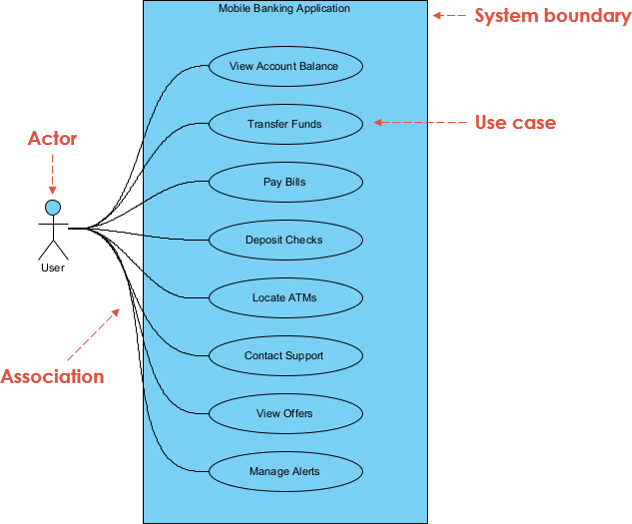
A use case description for the “Transfer Funds” use case in the mobile banking application:
Use Case Name: Transfer Funds
Actors: User
Summary: This use case allows the user to transfer funds between their own accounts or to other accounts.
Preconditions:
- The user must be logged in to the mobile banking application.
- The user must have at least one account set up in the application.
Basic Flow of Events:
- The user selects the “Transfer Funds” option from the main menu.
- The application presents the user with a list of their accounts and prompts them to select the account they want to transfer funds from.
- The user selects the account they want to transfer funds from.
- The application presents the user with a form to fill out with the recipient’s account information, including the account number and the name of the recipient.
- The user fills out the form and enters the amount they want to transfer.
- The application validates the recipient’s account information and the available balance in the user’s account.
- If the validation is successful, the application deducts the transfer amount from the user’s account and adds it to the recipient’s account.
- The application displays a confirmation message to the user with the details of the transfer.
Alternate Flows:
- 6a. If the recipient’s account information is invalid or the available balance in the user’s account is insufficient, the application displays an error message to the user and prompts them to correct the information or select a different account.
- 6b. If the user cancels the transaction before it is completed, the application returns to the main menu.
Postconditions:
- The funds have been successfully transferred from the user’s account to the recipient’s account.
- The user is presented with a confirmation message with the details of the transfer.
Here are the sequence diagrams for the normal, alternate, and exception flows of the “Transfer Funds” use case in the mobile banking application:
Normal Flow Sequence Diagram:
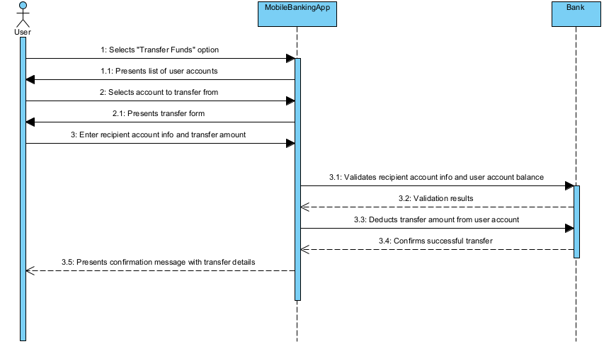
Alternate Flow Sequence Diagram (6a):
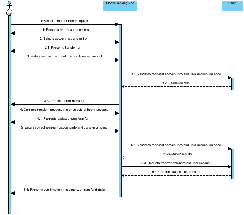
Alternate Flow Sequence Diagram (6b):
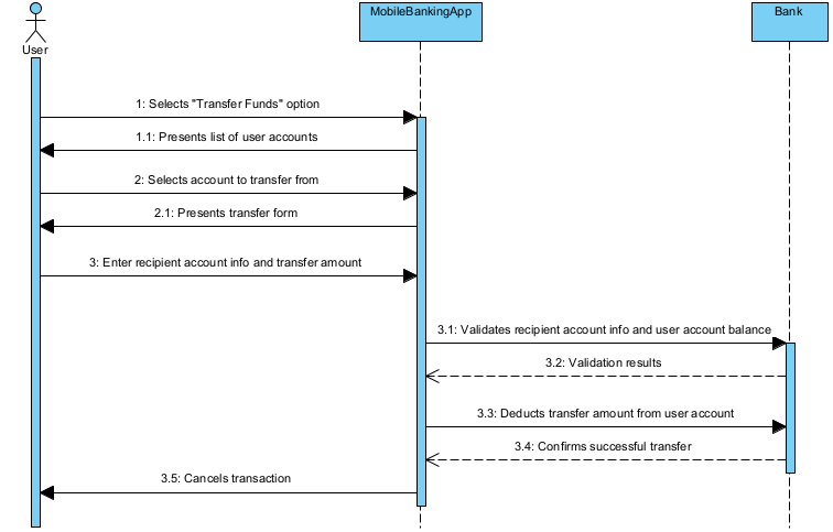
Now, lets elaborate only the normal flow sequence diagram into a more detailed MVC sequence diagram:
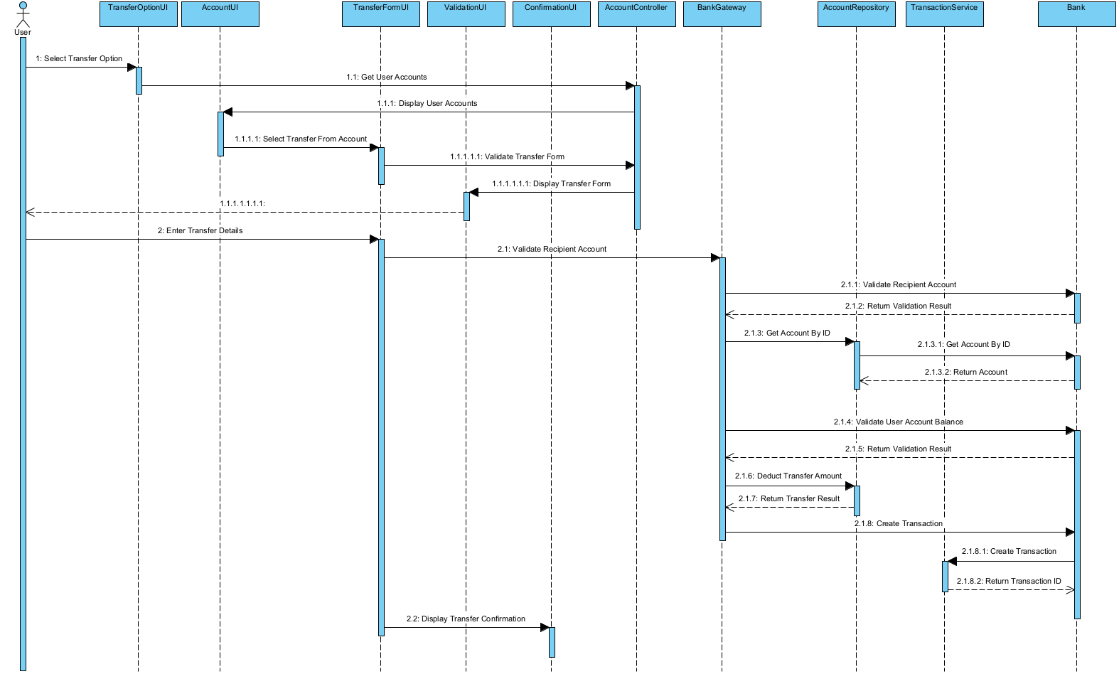
Using a use case-driven approach to create sequence diagrams helps ensure that the system is designed to meet the needs of the users and that the interactions between components are well-defined and efficient. Sequence diagrams are an essential tool in software design and development as they help to illustrate the interactions between objects or components within a system. A sequence diagram is a type of interaction diagram that depicts the flow of messages exchanged among objects or actors in a system. They are particularly useful in understanding and designing the behavior of a system in response to a specific use case. By developing a use case description with the flow of events section and then developing sequence diagrams for different scenarios, you can create a clear and comprehensive visualization of the system’s interactions.
Leave a Comment Cancel reply
Your email address will not be published. Required fields are marked *
Save my name, email, and website in this browser for the next time I comment.

- Visual Paradigm Online
- Request Help
- Customer Service
- Community Circle
- Demo Videos
- Visual Paradigm
- YouTube Channel
- Academic Partnership

p2: Use Case Diagram
You may also like.
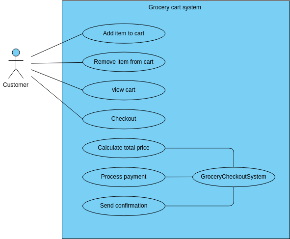
Create beautiful designs on-the-fly
No credit card required. No contracts to cancel. No downloads. No hidden costs.
©2024 by Visual Paradigm. All rights reserved.
- Terms of Service
- Privacy Policy
- Security Overview
- Hourly Consulting
- Intranet Portal
- Document Management
- Search Optimization
- Retention & Records Management
- Live Online Training
- On Demand Training
- Training Pricing
- Volume Licensing
- Engineering
- IT Providers
- Project Management
- Real Estate
- Newsletter Signup
How to create Hub Sites in SharePoint
It is hard to believe, but Hub Sites in SharePoint have been around since 2018 now. Hub Sites allow organizations to create meaningful site structures based on the company hierarchy so that users can easily access and navigate around the SharePoint sites. I published a step-by-step article back then on creating hub sites in SharePoint. However, just like with most features in SharePoint, Hub Sites improved in terms of additional functionalities. As such, I decided to write a new article to capture the latest features and nuances. Enjoy!
What is a Hub Site?
If you are new to the whole idea of Hub Sites, first, I would like to explain what the Hub Site is all about. As you create SharePoint sites in your Microsoft 365 tenant, they each have their own look & feel, design, URL, navigation, security, and content. However, sometimes you might want to navigate from one site to another easily, which is impossible without a few clicks. While you can create navigation links from one site to another, you have to do the same on the other site as well. With tens and possibly hundreds of sites your organization might have, this simply becomes impractical to maintain.
Luckily, we now have this Hub Site functionality. In simple terms, a Hub Site ties all these separate sites together via a common navigation. The idea behind the Hub Site is that you maintain the hub navigation on one site (parent site), and all the sites connected to the hub inherit that navigation (associated sites).

Example of the Hub Site Navigation in SharePoint
Use Cases for Hub Sites
There are plenty of use cases for Hub Sites. Essentially, whenever you want to create common navigation among multiple sites, you must create a Hub Site. Specifically, I would like to highlight the following use cases:
- Intranet Hub Site (Intranet Hub Sites with links to various department sites within an Intranet)
- Department Hub Site (A hub for a given department to link all the various department sites)
- Project Hub Site (A hub for PMO with links to all the different project sites)
Hub Site Limits
As of the writing of this post, according to Microsoft , the following hub limits exist:
- Max of 2,000 Hub Sites per tenant
- There is no limit on the number of associated sites per single Hub
While the limit above is a technical limit within SharePoint, you might wonder what the optimal hub structure should be and how many hub sites to create. I provided that guidance in this article .
Step 1: Register a site as a Hub
The first step in the process is to register a site as a Hub. This will be the “parent” site that will tie all the other sites together. This will ultimately be the site where you will manage hub navigation and hub theme (more on this later). Before following the instructions below, make sure that you will register a Communication site as a Hub . You do not want to choose a Team Site , since it implies restricted access. The parent Hub Site should be accessible by all the users within a Hub, and a Communication Site is always an excellent choice for this type of arrangement. To better understand the difference between a Team Site and a Communication site, read this article .

Step 2: Associate other sites to a Hub
The next step in the process is to associate a site (or multiple sites) with a Hub. This can be done from 2 places:
- SharePoint Admin Center
- SharePoint Site itself
It is important to note that a given site can only be associated with 1 hub at a time!
Associate a site to the Hub from the SharePoint Admin Center
To associate sites with a Hub from the Admin Center, do the following:
- Choose the Hub you want to connect to and click Save .
Associate a site to the Hub from a site itself
By default, any Site Owner can also connect to any hub within your environment. We can prevent this, I will explain how later in this article. But here are the steps for the Site Owner to connect their site to the Hub:
Step 3: Build Hub Navigation
The next step is to build out the Hub navigation. This is not something that happens automatically once the site is associated to the Hub. Hub Navigation can only be managed by the Hub Site Owner.
- Navigate to the main Hub Site
What happens when you create a Hub
It is important to note that when you create a Hub Site in SharePoint, it is not just the common navigation that the sites get. There are a few other important benefits.
Navigation Inheritance
Whatever navigation you create at the Hub Site (parent) level propagates all the way down to the associated sites. This is essentially why we have Hub Sites in the first place.

Example of Hub Navigation inherited from the Parent Hub Site
Theme and Header inheritance
Another essential element that propagates from the Hub Site to associated sites is a theme and header background color. This is a super important feature when you build, say, an Intranet Portal and want to ensure consistency in terms of branding, look, and feel.
Example of an error message when user tries to change a theme on an associated site
It is important to note that the site logo does not propagate. Just the Theme and Header color.
Hub Search Scope
Another thing that occurs is that an associated site becomes part of the Hub Search Scope. In other words, if you want to search the entire hub and all associated sites, you will see Search across sites, and that search box will search all sites that are connected to the hub. Of course, just like with anything in SharePoint, search results would be based on permissions to the associated sites.

Example of the Search Box from the Parent Hub Site
What DOES NOT happen when you create a Hub
It is equally important to note that some things users expect to be inherited or occur when you create a Hub do not actually happen. Specifically:
No impact on security & permissions
Contrary to popular belief, nothing happens to its permissions when you connect a site to a Hub. If you, say, connected a private/restricted Team Site to a Hub, Hub visitors will not get access to that restricted site. They will get an access denied message. There is a way to allow Hub Visitors to access the associated site, but this requires consent from both the Hub Owner and the Restricted Site Owner. More on this will be discussed at the bottom of this article.
No Site Logo inheritance
As mentioned above, there is no logo inheritance. You would need to manually change the logo on each site within a Hub.
No automatic navigation
As we already found out, the associated site does not magically get added to the Hub navigation. You have to add it manually. We covered this in Step 3 above.
Hub Data Aggregation/Roll-Up
There are other important benefits to creating Hubs. And they have to do with data aggregation and roll up. Certain Web parts allow you to aggregate content from associated sites within a Hub.
Roll up News in the Hub
If you utilize the News Web Part within the Hub Site and associated sites, you can roll up news and announcements from those sites and display them on the main Hub Site. This could be an invaluable mechanism for letting various Department Owners post news to their respective sites and then aggregate them all on an Intranet Homepage (Hub site).
Example of an extra source (All sites in the hub) option appearing within the News Web Part on Hub Sites
Roll up Events in the Hub
Likewise, we can roll up calendars from associated sites using the Events Web Part .
Example of an extra source (All sites in the hub) option appearing within the Events Web Part on Hub Sites
Roll up documents in the Hub (HCWP)
If you have ever used an HCWP web part , you can use it to roll up documents and other content from various sites. In the context of the Hub Sites, you can choose all sites within a Hub as a source.
Example of an extra source (All sites in the hub) option appearing within the HCWP Web Part on Hub Sites
Display all sites within a Hub (Sites Web Part)
This last trick is not so much a roll–up as another “hidden” benefit of Hub sites. If you add the Sites Web part to a Hub Site, it can automatically display all the sites that are part of the Hub!
Sites Web part in SharePoint
Example of an extra source (All sites in the hub) option appearing within the Sites Web Part on Hub Sites
Display of all Sites within the Hub using the Sites Web part in SharePoint
Optional Steps after Hub Site Creation
I decided to outline in this section optional steps that you might opt to implement based on your unique business requirements.
Add Hub Logo
Just like we can add a Site Logo , we can add a Hub Logo. It will appear to the left of the Hub Navigation. And it does serve its purpose. No matter where you are within a Hub (any site), clicking on the Hub Logo will take you to the Hub Site (parent site).
Set up Audience Targeting
The next thing you can do is set up Audience Targeting . This is handy if you connect restricted/private sites to the hub and do not want them to be displayed in the navigation for users who do not have access. By default, the labels and links you add to Hub Navigation will be visible to all the visitors. However, based on permissions, you can target them to specific audiences (groups). This feature will allow you to personalize the navigation menu based on who is logged in. I explain how to set up navigation Audience Targeting in this article .
Sync Hub Permissions
To be honest, this next step is not something I endorse. As mentioned earlier, when you connect a site to the hub, it does nothing to its permissions. However, if you want to quickly allow Hub Site Visitors to get read-only access to the associated sites, you can do so with the Sync Hub Permissions feature. I blogged about it previously .
It is important to note that even if you enable it, each site owner must manually sync their site’s permissions and enable the feature. This way, if you are a Site Owner of a private/restricted site, you still control/access your site, not the Hub Site Owner!
Set up who can connect/associate sites to the Hub
The next setting that might be worthwhile to implement (especially if you are part of a large organization) is to configure who can connect (associate) sites to your Hub. By default, any site owner can associate their site with any hub! So, if you do not want any unwelcome guests in your portal, you might want to tweak those settings.
There are 2 ways to prevent users from connecting to the Hub:
- By specifying users within the SharePoint Admin Center
- By creating an approval workflow for Hub Connection requests
I documented both options here .
Example of an approval workflow for Hub Association
Example of Hub Approved Users who can associate sites to the Hub (set up in SharePoint Admin Center)
Embed a Hub within another Hub
Another thing you can do with Hubs is nest them. This might become necessary if you have several Hubs in your tenant and want to mimic the organization structure. For example, you have a Hub for a Business Unit, Region, or Department and would like to nest it inside the Corporate/Intranet Hub. I explained how to nest hubs and the important nuances/limitations here .
Register a Hub Site as a Home Site
This step might only be necessary if your Hub happens to be an Intranet Site/portal and you would like to promote it as the leading site in your organization. You can register the Hub Site as a Home Site to do this. This will allow your site to later be included in Viva Connections , SharePoint App Bar , etc.
Check Hub Usage
Finally, when you register a site as a Hub, you get an aggregated Site Usage Analytics Report, accessible from the Site Usage . While you can get analytics for individual sites, when you choose the Hub option, it gives you analytics for the whole Hub and its sites. It might be handy in some cases.
I’m Greg Zelfond, a U.S. based SharePoint consultant, and I provide affordable out-of-the-box SharePoint consulting, training, and configuration assistance to small and medium-sized businesses all over the world.
Share Article
- Share on Twitter
- Share on LinkedIn
- Share on Facebook

2 ways to organize department news on your SharePoint Hub
One of the primary goals of the Intranet portals is, of course, to share the news and announcements within the organization. SharePoint has some fantastic options available in this area,…

How to disable subsite creation in SharePoint Online
I can’t believe it took me all these years to write this post finally. But today, it is time for all of us to say goodbye to subsites in SharePoint…

How to associate a Hub to another Hub in SharePoint Online
It has been more than three years since Hub functionality made its debut in SharePoint Online. One of my first posts on the topic provides detailed instructions on doing just…

IMAGES
VIDEO
COMMENTS
Learn how to create use case diagrams to analyze and visualize the interactions between actors and systems. Follow the steps, guidelines and templates to draw effective use case diagrams for various scenarios.
Learn how to create use case diagrams in UML to show the interactions between users and systems. Find out the components, symbols, notation, and examples of use case diagrams with Lucidchart.
Learn what a use case diagram is, how to draw one, and see examples of use case diagrams. A use case diagram shows the interactions between actors and a system to achieve goals.
Learn how to make Use Case Diagrams in this tutorial. Both beginners and intermediate UML diagrammers will find all the necessary training and examples on sy...
Learn what a use case diagram is, why to make them, and how to draw them with SmartDraw. Find examples, symbols, tips, and tutorials for creating UML diagrams.
Begin by dragging a system boundary box onto your canvas. In Lucidchart, this shape is labeled as a rectangle container. In a development use case, systems represent what you are developing, such as a software component or a complete suite. Next, focus on the actors. Your use case diagram should reflect the actor's perspective, so ask yourself ...
Change the status to Use Case Diagram 'started' to facilitate progress tracking of each System. Understand the system by referring to the brief and scope of the System detailed in the 'List of System' section of the document. Step 1: Draw the System Boundary and name the system. Step 2:
A use case diagram is a graphical representation used in use case modeling to visualize and communicate these interactions and relationships. In a use case diagram, you'll typically see actors represented as stick figures, and the use cases (specific functionalities or features) as ovals or rectangles. Lines and arrows connect the actors to ...
Learn how to create use case diagrams to communicate system functionality with actors and use cases. Follow the steps and see the examples to draw your own diagrams online with Gliffy.
A Use case diagram is part of the Unified modeling language, and is used by developers to see the interaction between the end users of their program and their system. To put more simply, we can say that this type of diagram is the blueprint of the entire interaction between the user and a specific system. There are many elements involved when ...
Learn how to use Visio to create a UML use case diagram that summarizes how users interact with a system. Follow the steps to add shapes, connectors, and subsystems to the diagram.
Learn how to create and design use case diagrams, a visual representation of how users interact with a system. Follow the steps, notations, relationships, and examples to draw your own diagrams.
Learn what a use case diagram is and how to create one with Venngage's Diagram Maker and templates. See examples of different types of use case diagrams for various systems and scenarios.
How to make a use case diagram. In Lucidchart, creating a use case diagram from scratch is surprisingly simple. Create a use case scenario document to organize the process and all possible alternative extensions. Open a blank Lucidchart document or start with a template and enable the UML shape library. Select the shape you want and drag out ...
The use case title is entered into the label in the top left. Use the Frame shape from the UML shape library - hover over any shape to see a larger preview. Make sure you send frame and bounding box shapes to the back (select them then press Ctrl+Shift+B) so you can keep working with the other shapes in your diagram.
Use case diagrams are a way to capture the system's functionality and requirements in UML diagrams. It captures the dynamic behavior of a live system. A use case diagram consists of a use case and an actor. A use case represents a distinct functionality of a system, a component, a package, or a class. An actor is an entity that initiates the ...
Use case diagrams in UML are used during the requirements phase of software development - they usually put the system requirements into a diagram format, and it's easy to see what actions a system must support at a glance. Of course, there will be many use cases for your system, and therefore you will usually ...
Brainstorm with the best of them. Your team is your most precious resource. Analyze and render use cases together without the hassle—FigJam templates are full-blown digital meeting spaces, complete with easy-to-use tools and widgets like sticky notes, polls, and comment boxes that make feedback fun. Start diagramming.
Create Use Case Diagram online. The UML software provided by VP Online lets you create beautiful use case diagrams in a snap. Create use case diagrams easily with the drag and drop editor, design with the rich set of UML symbols, keep your design in a cloud workspace and work collaboratively with your team. You can also export and share your ...
A use case is a description of a particular interaction between a user and the system. Some examples of use cases might include logging in, making a purchase, or updating a user profile. Step 2: Create a use case diagram. Once you have identified the key use cases for the system, you can create a use case diagram to represent them visually.
To create an Use Case: Select Use Case in Toolbox. Drag on the diagram as the size of Use Case. To create an Use Case (model element only) by Menu: Select an Element where a new Use Case to be contained. Select Model | Add | Use Case in Menu Bar or Add | Use Case in Context Menu. You can use QuickEdit for Use Case by double-click or press Enter ...
This is not the purpose of use-case diagrams, and could be modelled better with other techniques (e.g. activity diagram). use-cases should not have any sequential ordering, and «extend» should not be used to represent that a functionality is called from another. Moreover, generalisation should only be used when the specialised use-case could ...
Movie Ticket Booking System Use Case Diagram. Online Education Platform Use Case Diagram . Fitness Tracking App Use Case Diagram . Ride Sharing App Use Case Diagram. Restaurant management use case diagram. Online booking use case diagram. Travel booking use case diagram.
Use Cases for Hub Sites. There are plenty of use cases for Hub Sites. Essentially, whenever you want to create common navigation among multiple sites, you must create a Hub Site. Specifically, I would like to highlight the following use cases: Intranet Hub Site (Intranet Hub Sites with links to various department sites within an Intranet)