
Norton’s Theorem with solved problem
Norton’s theorem is used to solve complex circuits consisting of several sources and impedances by converting them into a simple equivalent circuit called Norton’s equivalent circuit. Now let’s look at the statement.
Norton’s Theorem states that
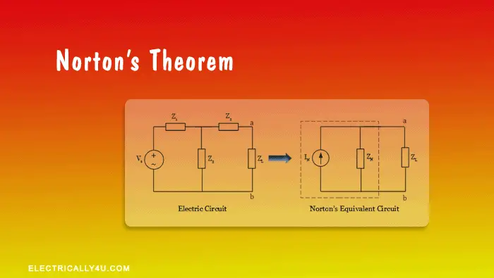
“ Any linear bilateral circuit containing several energy sources and impedance s can be replaced with an equivalent circuit consisting of single Norton’s current source in parallel with Norton’s impedance connected across the load impedance“.
Norton’s equivalent circuit has a single current source called Norton’s current source(IN), an equivalent impedance called Norton’s equivalent impedance Z N , and a load impedance Z L .

In the above equivalent circuit, Norton’s current IN is nothing but a short-circuit current, which is obtained by shorting the load impedance Z L .
Norton’s equivalent impedance ZN is obtained by the same procedure followed in Thevenin’s theorem. The equivalent impedance is obtained by short-circuiting all the voltage sources, open-circuiting all the current sources in the circuit, and removing the load resistor from the circuit.
Now, let us look at the step-by-step procedure to determine the I N and Z N in the above circuit.
Procedure to determine Norton’s equivalent circuit
Step 1 – determination of norton’s current.
Remove the load impedance Z L in the given electric circuit and short it by joining the terminal ‘ab’ with a line as shown in the below figure.

Now, in the following figure, we need to find the current I N that is flowing in the terminal ab. To find this current, it is necessary to determine the total current in the circuit. The total current I T can be determined by using Ohm’s law ,
![\[I_T = \frac{V_s}{Z_{eq}} \]](https://www.electrically4u.com/wp-content/ql-cache/quicklatex.com-c86c1210c8bf68b141db56461ea0d0d7_l3.png "Rendered by QuickLaTeX.com")
From the obtained value of total current I T , the current through the impedance Z 2 (or Norton’s current I N ) is determined by using the current division rule .
![\[I_N = I_T .\frac{Z_3}{Z_2 + Z_3}\]](https://www.electrically4u.com/wp-content/ql-cache/quicklatex.com-6a4df4dadcae4bda08253f8452718baa_l3.png "Rendered by QuickLaTeX.com")
Step 2 – Determination of Norton’s Impedance
Since there is only one voltage source available in the circuit, remove the voltage source, short the voltage terminals, and remove the load impedance, as shown in the figure below.

The Norton’s equivalent impedance is obtained from terminal ab using the formula,
![\[Z_N = \frac{Z_1 . Z_3}{Z_1 + Z_3} + Z_2 \]](https://www.electrically4u.com/wp-content/ql-cache/quicklatex.com-41785b468cc53b23bf83057710a6cdca_l3.png "Rendered by QuickLaTeX.com")
Step 3 – Formation of Norton’s equivalent circuit
Using the obtained values of V N and Z N , the equivalent circuit is drawn below. This circuit is called Norton’s equivalent circuit.

Now, from this circuit, the current through the load I L can be determined by using the current division rule . It is given by,
![\[ I_L = I_N . \frac{Z_N}{Z_N + Z_L} \]](https://www.electrically4u.com/wp-content/ql-cache/quicklatex.com-f8587707e0d00931d89fa308a153258c_l3.png "Rendered by QuickLaTeX.com")
Solved Problem 1
For the given circuit, determine the current flowing through 10 Ω resistor using Norton’s theorem.

Since the question here, is to determine the current through 10 Ω resistor, it is considered as the load.
(a) To find Norton’s current , Remove the load resistor(10 Ω), short it with a wire and the circuit is redrawn as below.

In this circuit, we need to find the current I N , which is Norton’s current flowing from a to b. To find the value of I N , it is necessary to determine the total current in the circuit.
![\[ R_{eq} = 1 + \frac{3 * 2}{3 + 2} = 2.2 \Omega \]](https://www.electrically4u.com/wp-content/ql-cache/quicklatex.com-e0c4578025c866ccd5a751a807407f32_l3.png "Rendered by QuickLaTeX.com")
Now, the total current I T is given by,
![\[ I_T = \frac{V_s}{R_{eq}} = \frac{9}{2.2} = 4.09 A\]](https://www.electrically4u.com/wp-content/ql-cache/quicklatex.com-b98799827039ec41062df7aba5481015_l3.png "Rendered by QuickLaTeX.com")
The current through the 2 Ω resistor (or Norton’s current I N ) is obtained by applying the current division rule,
![\[I_N = I_T * \frac{3}{3 + 2} = 4.09 * \frac{3}{5} = 2.454 A \]](https://www.electrically4u.com/wp-content/ql-cache/quicklatex.com-e5fdf558127d55e76d2897a67b576153_l3.png "Rendered by QuickLaTeX.com")
(b)To find Norton’s resistance, Remove the load resistor, short the voltage source and the circuit is redrawn as below.

In this circuit, we can observe that the 2 Ω resistor is in series with the parallel combination of 1 Ω and 3 Ω resistors. Thus the equivalent value of resistance is obtained as,
![\[R_{N} = 2 + \frac{1 * 3}{1 + 3} = 2.75 \Omega \]](https://www.electrically4u.com/wp-content/ql-cache/quicklatex.com-45a3704a08b3568384b188fe29362b88_l3.png "Rendered by QuickLaTeX.com")
[ Learn how to find the equivalent resistance of resistor when they are connected in series and parallel. ]
(c)Norton’s Equivalent Circuit. It is drawn by connecting Norton’s voltage I N , Norton’s resistance R N and load resistor in series, as shown below

From this circuit, the current through the load R L = 10 Ω resistor is obtained using current division rule . It is given by,
![\[ I_L = I_N * \frac{R_N}{R_N + R_L} = 2.454 * \frac{2.75}{2.75 + 10} = 0.529 A \]](https://www.electrically4u.com/wp-content/ql-cache/quicklatex.com-8fbeb714049505fca86fb728416219ee_l3.png "Rendered by QuickLaTeX.com")
Please enable JavaScript
Solved Problem 2
Determine the current through AB in the given circuit using Norton’s theorem.

Since the question here is to find the current through AB, 6 Ω resistor is considered as the load.
(a) To find Norton’s current , Remove the load resistor(6 Ω), short it with a wire and the circuit is redrawn as below.

In this circuit, we need to find the current I N through path AB. Since path AB has low resistance, maximum current will flow through this path. Hence the circuit can be reduced and drawn as below,

From this circuit, The current flowing through path AB, i.e., Norton’s current, I N = 30 A .
(b)To find Norton’s resistance, Remove the load resistor, open the current source and the resulting circuit is redrawn as below.

When you observe this circuit, there will not be any current flow through 10 Ω resistor, as it is open. Also, 3 Ω resistor and 1 Ω resistor are in parallel with each other, the combination of which is in series with 2 Ω resistor. The circuit can be redrawn as,

The Norton’s equivalent resistance can be obtained as,
![\[R_N = \frac{4 * 2.75}{4 + 2.75} = 1.63 \Omega \]](https://www.electrically4u.com/wp-content/ql-cache/quicklatex.com-6eae0fd37147cbfb7f20fb2bbc03a5ee_l3.png "Rendered by QuickLaTeX.com")
From this circuit, the current through the load R L = 6 Ω resistor is obtained using current division rule . It is given by,
![\[ I_L = I_N * \frac{R_N}{R_N + R_L} = 30 * \frac{1.63}{1.63 + 6} = 6.409 A \]](https://www.electrically4u.com/wp-content/ql-cache/quicklatex.com-0aa6a29c81ef8e70a671cd813d3c6a69_l3.png "Rendered by QuickLaTeX.com")
Sharing is Caring

An Assistant Professor in the Department of Electrical and Electronics Engineering, Certified Energy Manager, Photoshop designer, a blogger and Founder of Electrically4u.
Related Posts

Leave a Reply Cancel reply
Your email address will not be published. Required fields are marked *
Save my name, email, and website in this browser for the next time I comment.
Sir, But when we solved the first problem by Thevenin’s theorem we got the current through load resistance as 0.84 A but when we solved the same circuit with Norton’s theorem we got the current through load resistance as 0.52 A. Now I am confused, I think we should get same amount of current through load resistance. Please correct me and reply.
You will get the same amount of current through load resistance, when it is solved by using Thevenin’s theorem. I have solved the same problem using Thevenin’s theorem. Check this solved problem .
Subscribe to Electrically4u..!
Enter your Email Address to get all our updates about new articles to your inbox.

- Switch skin
Home > Circuit Analysis > Norton’s Theorem. Easy Step by Step Procedure with Example
Norton’s Theorem. Easy Step by Step Procedure with Example
Norton’s theorem in dc circuit analysis.
Norton’s theorem is another useful technique to analyze electric circuits like using the Thevenin’s Theorem , which reduces linear , active circuits and complex networks into a simple equivalent circuit. The main difference between Thevenin’s theorem and Norton’s theorem is that, Thevenin’s theorem provides an equivalent voltage source and an equivalent series resistance, while Norton’s theorem provides an equivalent Current source and an equivalent parallel resistance.
Norton’s Theorem states that:
Any linear electric network or complex circuit with current and voltage sources can be replaced by an equivalent circuit containing a single independent current source I N and a parallel resistance R N .
In other but simple words, Any linear circuit is equivalent to a real and independent current source in specific terminals.
Related Post: Thevenin’s Theorem. Easy Step by Step Procedure with Example (Pictorial Views)
Steps to Analyze an Electric Circuit using Norton’s Theorem
- Short the load resistor.
Calculate / measure the Short Circuit Current. This is the Norton Current (I N ).
- Open Current Sources, Short Voltage Sources and Open Load Resistor.
- Calculate /measure the Open Circuit Resistance. This is the Norton Resistance (R N ).
- Now, Redraw the circuit with measured short circuit Current (I N ) in Step (2) as Current Source and measured open circuit resistance (R N ) in step (4) as a parallel resistance and connect the load resistor which we had removed in Step (3). This is the Equivalent Norton Circuit of that Linear Electric Network or Complex circuit which had to be simplified and analyzed. You have done it.
- Now find the Load current flowing through and Load Voltage across Load Resistor by using the Current divider rule . I L = I N / (R N / (R N + R L )) ((For clear explanation … check the solved example given below).
Solved Example by Norton’s Theorem:
Find R N , I N , the current flowing through and Load Voltage across the load resistor in fig (1) by using Norton’s Theorem.

Solution:-
Short the 1.5Ω load resistor as shown in (Fig 2).

We have shorted the AB terminals to determine the Norton current, I N. The 6Ω and 3Ω are then in parallel and this parallel combination of 6Ω and 3Ω are then in series with 2Ω.
So the total resistance of the circuit to the Source is:-
2Ω + (6Ω || 3Ω) ….. (|| = in parallel with).
R T = 2Ω + [(3Ω x 6Ω) / (3Ω + 6Ω)] → I T = 2Ω + 2Ω = 4Ω.
I T = V ÷ R T
I T = 12V ÷ 4Ω
Now we have to find I SC = I N … Apply CDR… (Current Divider Rule)…
I SC = I N = 3A x [(6Ω ÷ (3Ω + 6Ω)] = 2A.
I SC = I N = 2A.

Open Current Sources, Short Voltage Sources and Open Load Resistor. Fig (4)

Calculate /measure the Open Circuit Resistance. This is the Norton Resistance (R N )
We have Reduced the 12V DC source to zero is equivalent to replace it with a short in step (3), as shown in figure (4) We can see that 3Ω resistor is in series with a parallel combination of 6Ω resistor and 2Ω resistor. i.e.:
3Ω + (6Ω || 2Ω) ….. (|| = in parallel with)
R N = 3Ω + [(6Ω x 2Ω) ÷ (6Ω + 2Ω)]
R N = 3Ω + 1.5Ω

Connect the R N in Parallel with Current Source I N and reconnect the load resistor. This is shown in fig (6) i.e. Norton Equivalent circuit with load resistor.

Now apply the last step i.e. calculate the load current through and Load voltage across the load resistor by Ohm’s Law as shown in fig 7.
Load Current through Load Resistor…
I L = I N x [R N ÷ (R N + R L )]
= 2A x (4.5Ω ÷ 4.5Ω + 1.5Ω) → = 1.5A
I L = 1. 5A
Load Voltage across Load Resistor…
V L = I L x R L
V L = 1.5A x 1.5Ω
V L = 2.25V

Now compare this simple circuit with the original circuit given in figure 1. Can you see how much easier it will be to measure/calculate the load current and load Voltage for different load resistors through Norton’s Theorem even in much more complex circuits? Only and only yes.
Good to know: Both Norton’s & Thevenin’s theorems can be applied to both AC and DC circuits containing difference components such as resistors , inductors and capacitors etc. Keep in mind that the Norton’s current “I N ” in AC circuit is expressed in complex number (polar form) whereas, the Norton’s resistance “R N ” is stated in rectangular form.
- Maximum Power Transfer Theorem for AC & DC Circuits
- Kirchhoff’s Current & Voltage Law (KCL & KVL) | Solved Example
- Compensation Theorem – Proof, Explanation and Solved Examples
- Substitution Theorem – Step by Step Guide with Solved Example
- Millman’s Theorem – Analyzing AC & DC Circuits – Examples
- Superposition Theorem – Circuit Analysis with Solved Example
- Tellegen’s Theorem – Solved Examples & MATLAB Simulation
- SUPERNODE Circuit Analysis | Step by Step with Solved Example
- SUPERMESH Circuit Analysis | Step by Step with Solved Example
- Voltage Divider Rule (VDR) – Solved Examples for R, L and C Circuits
- Current Divider Rule (CDR) – Solved Examples for AC and DC Circuits
- Star to Delta & Delta to Star Conversion. Y-Δ Transformation
Electrical Technology
Related articles.

How to Size a Single Phase and Three Phase Transformer in kVA? Calculator

How to Calculate the Battery Charging Time & Battery Charging Current – Example

How To Calculate Your Electricity Bill. Electric Bill Calculator with Examples

How to Find the Proper Size of Wire & Cable: Metric & Imperial Systems

Thevenin’s Theorem. Step by Step Procedure with Solved Example

Automatic Street Light Control Circuit using LDR & Transistor BC 547
24 comments.
sir plz give me a name of books about circuit and analysis of network for clearing concepts.<br />
WH Hayt and JE Kemmerly Engineering circuit analysis
basic electronics by b l theraja
If we have to find the current through voltage source with 10ohm resistir are connected in series then how to find the Zl i.e load impedence
Great article! Norton's Theorem can certainly be confusing for a beginner.
great and thanku<br />
Thanks a lot
Nortons theorem
I want to know the best refarance book which can give me the best concept about nortons / Thevein , super position theorem If u can pls help me Thank you
Pls,why did they use (3/(3 6)) to solve for the nortons cuRrent
May you please help with the best book I can use for electrical engineering technology
Sadique 11th edition
Thanks dude…..i hve exam in 3 hrs……ur post’s helped me a lot!!!
I’m glad it helped you. Lots of best wishes & prayers for your success!
Thanks sir a lot of thanks
why the CDR are not (RT / RX+RT) X IT make me confuse ?
What if u r to find the current across the 6(ohm) resister?
Thank you so much
Nortom resistence is not calculated correctly mine give 4.5 ohm, you have calculated as seen from the battery
Very informative. really good website. never thought I would get hand made notes like content on a website. Keep it up guys.
Thanks for your clear information ??
Stepwise answer is very important and you do it well .i understand the problems easily .
The bestt explanation i have come across so far..thank youu mann
I’m glad it helped… Best regards.
Leave a Reply Cancel reply
Your email address will not be published. Required fields are marked *

What is Norton’s Theorem and Norton’s Equivalent Circuit?
This article covers norton’s theorem and norton’s equivalent circuit parameters, such as norton’s equivalent resistance and short-circuit current, along with norton’s theorem solved problem with dependent sources., what is norton’s theorem.
Norton’s Theorem states that any two-terminal electric network comprising resistances and voltage and/or current sources may be substituted with a single current source connected in a parallel configuration with a single resistance. The current source output is the short-circuit current at the terminals of a network, whereas the parallel resistance is the resistance between the terminals of a network when all the sources are set to zero.
Find the Norton’s Equivalent Circuit
Suppose we are given an arbitrary circuit containing any or all of the following elements: resistors, voltage sources, and current sources (the source can be dependent as well as independent). Let us identify a pair of nodes, say nodes a and b, such that the circuit can be partitioned into two parts, as shown in Figure 1.
Figure.1: Circuit partitioned into two parts
Furthermore, suppose that circuit A contains no dependent source that is dependent on a variable in circuit B, and vice versa. Then, we can model circuit A by an appropriate independent current source, call it i sc , which is connected in parallel with an appropriate resistance, call it R N . This parallel combination of a current source and resistance is called Norton’s equivalent of circuit A . In other words, circuit A in Figure 1, and the circuit in the shaded box in Figure 2 have the same effect on circuit B. This result is known as Norton’s theorem.
Figure.2: Norton’s Equivalent Circuit
Circuit B (which is often called a load) may consist of many circuit elements, a single element ( a load resistor), or no element.
- You May Also Read: Thevenin’s Theorem with Solved Examples
Norton’s Short Circuit Current
To obtain Norton’s equivalent of some circuit A, determine the short-circuit current i sc by placing a short circuit between nodes a and b and then calculate the resulting current (directed from the terminal a to b through the short circuit).
Figure.3 (a): Determination of short-circuit current
How to Find Norton’s Equivalent Resistance
There are several ways to find Norton’s equivalent resistance, which are given below:
1 . To obtain the resistance R N – called Norton’s equivalent resistance of circuit A: I. Remove circuit B from circuit A. II. Set all independent sources in circuit A to zero. (A zero voltage source is equivalent to a short circuit, and a zero current source is equivalent to an open circuit). III. Determine the resistance between nodes a and b- this is R N – as shown in figure 3(b).
Figure.3 (b): Determination of Norton’s Equivalent Resistance
2. Short-circuit the terminals a and b, then find the short-circuit current I sc . Norton’s equivalent resistance is given by
\[{{\text{R}}_{\text{N}}}\text{ = }{{\text{V}}_{\text{oc}}}\text{/}{{\text{I}}_{\text{sc}}}\text{ = }{{\text{V}}_{\text{th}}}\text{/}{{\text{I}}_{\text{sc}}}\]
Whereas V oc or V th can be found as was done for the Thevenin equivalent circuit. 3. When the source network has a ladder structure and contains no controlled (dependent) sources, R N is easily found by series-parallel reduction of the dead network. When the source network contains controlled sources, Norton’s equivalent resistance can be found using the method represented in figure 4.
Figure.4: Find Norton’s Equivalent Resistance
Here, the dead source network has been connected to an external test source. This test source may be any independent voltage or current source that establishes v o and it at the terminals. Since the dead network contains only resistors and controlled sources, and since R N equals the equivalent resistance of the dead network, the equivalent resistance theorem tells us that
\[{{\text{R}}_{\text{N}}}\text{=}{{\text{v}}_{\text{o}}}\text{/}{{\text{i}}_{\text{o}}}\]
Norton’s Theorem Solved Example
Let’s find Norton Equivalent resistance R N
- Open circuit all current sources
- Short circuit all voltage sources
Now, we have the following circuit to calculate R N
\[{{R}_{N}}=\text{ }5||\text{ }\left( 8+4+8 \right)\]
\[{{R}_{N}}=4\text{ }\Omega \]
In order to find short-circuit current i sc , we short-circuit terminals a and b:
Using loop analysis we have;
\[{{i}_{1}}=2A\]
$20{{i}_{2}}-4{{i}_{1}}-12=0$
\[{{i}_{2}}=1A\]
\[{{I}_{N}}={{i}_{sc}}={{i}_{2}}=1A\]
Hence we have followed Norton’s equivalent circuit
Norton’s Theorem Solved Problem with Dependent Sources
We will find I sc and R N for the circuit shown in the following figure.
In order to determine the short-circuit current, we’ll short-circuit terminals a and b as shown in the following figure and V 2 = 0.
Apply KCL to node 1:
\[\begin{matrix} -0.003+\frac{{{V}_{1}}}{3000}+\frac{{{V}_{1}}}{2000}=0 & \cdots & (1) \\\end{matrix}\]
Multiplying (1) by 6000 yields:
\[\begin{align} & 5{{V}_{1}}=\text{ }18 \\ & {{V}_{1}}=\text{ }3.6\text{ }V \\\end{align}\]
Now, calculating currents:
\[i=\text{ }{{V}_{1}}/3000\text{ }=\text{ }3.6\text{ }V/3000\Omega =\text{ }0.0012\text{ }A\]
\[{{V}_{CCVS}}=\text{ }2000i\text{ }=\text{ }2.4\text{ }V\]
\[{{I}_{{{R}_{2}}}}=\text{ }{{V}_{1}}/{{R}_{2}}=1.8mA\]
\[{{I}_{{{R}_{3}}}}=\text{ }{{V}_{CCVS}}/{{R}_{3}}=2.4mA\]
Finally, I N would be
\[{{I}_{N}}={{I}_{{{R}_{2}}}}+\text{ }{{I}_{{{R}_{3}}}}~=\text{ }1.8mA+\text{ }2.4mA=\text{ }4.2mA\]
\[{{I}_{{{R}_{2}}}}=i={{V}_{t}}/({{R}_{1}}+\text{ }{{R}_{2}})\text{ }=\text{ }1\text{ }V/5\text{ }k\Omega =0.2mA\]
\[{{V}_{CCVS}}=\text{ }2000i\text{ }=\text{ }0.4\text{ }V\]
\[{{I}_{{{R}_{3}}}}=\text{ }({{V}_{t}}\text{- }{{V}_{CCVS}})/{{R}_{3}}=0.6mA\]
\[{{I}_{{{R}_{4}}}}={{V}_{t}}/{{R}_{4}}=0.25mA\]
\[{{I}_{t}}={{I}_{{{R}_{2}}}}~+{{I}_{{{R}_{3}}}}~+{{I}_{{{R}_{4}}}}=\text{ }0.2mA+\text{ }0.6mA+\text{ }0.25mA=\text{ }1.05mA\]
Noe, Norton’s equivalent resistance can be found as
\[{{R}_{N}}={{V}_{t}}/{{I}_{t}}=\text{ }952.381\Omega \]
Summary of Norton’s Theorem Steps
The following steps can be carried out for solving a circuit using Norton’s Theorem :
- The Portion of the circuit considered as the load is removed
- The short circuit current i sc is calculated at terminals
- To calculate R N :
- Short circuit all independent voltage sources
- Open circuit all independent current sources
- Draw Norton’s equivalent circuit, connect the load, and calculate the load current.
Leave a Comment Cancel reply
You must be logged in to post a comment.

- school Campus Bookshelves
- menu_book Bookshelves
- perm_media Learning Objects
- login Login
- how_to_reg Request Instructor Account
- hub Instructor Commons
Margin Size
- Download Page (PDF)
- Download Full Book (PDF)
- Periodic Table
- Physics Constants
- Scientific Calculator
- Reference & Cite
- Tools expand_more
- Readability
selected template will load here
This action is not available.
5.4: Thévenin's and Norton's Theorems
- Last updated
- Save as PDF
- Page ID 25268

- James M. Fiore
- Mohawk Valley Community College
\( \newcommand{\vecs}[1]{\overset { \scriptstyle \rightharpoonup} {\mathbf{#1}} } \)
\( \newcommand{\vecd}[1]{\overset{-\!-\!\rightharpoonup}{\vphantom{a}\smash {#1}}} \)
\( \newcommand{\id}{\mathrm{id}}\) \( \newcommand{\Span}{\mathrm{span}}\)
( \newcommand{\kernel}{\mathrm{null}\,}\) \( \newcommand{\range}{\mathrm{range}\,}\)
\( \newcommand{\RealPart}{\mathrm{Re}}\) \( \newcommand{\ImaginaryPart}{\mathrm{Im}}\)
\( \newcommand{\Argument}{\mathrm{Arg}}\) \( \newcommand{\norm}[1]{\| #1 \|}\)
\( \newcommand{\inner}[2]{\langle #1, #2 \rangle}\)
\( \newcommand{\Span}{\mathrm{span}}\)
\( \newcommand{\id}{\mathrm{id}}\)
\( \newcommand{\kernel}{\mathrm{null}\,}\)
\( \newcommand{\range}{\mathrm{range}\,}\)
\( \newcommand{\RealPart}{\mathrm{Re}}\)
\( \newcommand{\ImaginaryPart}{\mathrm{Im}}\)
\( \newcommand{\Argument}{\mathrm{Arg}}\)
\( \newcommand{\norm}[1]{\| #1 \|}\)
\( \newcommand{\Span}{\mathrm{span}}\) \( \newcommand{\AA}{\unicode[.8,0]{x212B}}\)
\( \newcommand{\vectorA}[1]{\vec{#1}} % arrow\)
\( \newcommand{\vectorAt}[1]{\vec{\text{#1}}} % arrow\)
\( \newcommand{\vectorB}[1]{\overset { \scriptstyle \rightharpoonup} {\mathbf{#1}} } \)
\( \newcommand{\vectorC}[1]{\textbf{#1}} \)
\( \newcommand{\vectorD}[1]{\overrightarrow{#1}} \)
\( \newcommand{\vectorDt}[1]{\overrightarrow{\text{#1}}} \)
\( \newcommand{\vectE}[1]{\overset{-\!-\!\rightharpoonup}{\vphantom{a}\smash{\mathbf {#1}}}} \)
These theorems are related in that they allow complex linear networks to be simplified down to a single source with an associated internal impedance. They simplify analysis when checking a circuit with multiple possible loads.
Thévenin's Theorem
Thévenin's theorem is named after Léon Charles Thévenin. It states that:
\[\text{Any single port linear network can be reduced to a simple voltage source, } E_{th}, \text{ in series with an internal impedance } Z_{th}. \nonumber \]
It is important to note that a Thévenin equivalent is valid only at a particular frequency. If the system frequency is changed, the reactance and impedance values will change and the resulting \(E_{th}\) and \(Z_{th}\) values will be altered. Consequently, these equivalents are generally not appropriate for a circuit using multiple sources with differing frequencies 1 . A generic example of a Thévenin equivalent is shown in Figure \(\PageIndex{1}\).

The phrase “single port network” means that the original circuit is cut in such a way that only two connections exist to the remainder of the circuit. That remainder may be a single component or a large multi-component sub-circuit. \(E_{th}\) is the open circuit voltage at the port and \(Z_{th}\) is the impedance looking back into the port (i.e., the equivalent that now drives the remainder). As there are many ways to cut a typical circuit, there are many possible Thévenin equivalents. Consider the circuit shown in Figure \(\PageIndex{2}\).

Suppose we want to find the Thévenin equivalent that drives \(R_2\). We cut the circuit immediately to the left of \(R_2\). That is, The first step is to make the cut, removing the remainder of the circuit. In this case the remainder is just \(R_2\). We then determine the open circuit output voltage at the cut points (i.e., at the open port). This voltage is called the Thévenin voltage, \(E_{th}\). This is shown in Figure \(\PageIndex{3}\). In a circuit such as this, basic series-parallel analysis techniques may be used to find \(E_{th}\). In this circuit, due to the open, no current flows through the inductor, \(L\), and thus no voltage is developed across it. Therefore, \(E_{th}\) must equal the voltage developed across the capacitor, \(C\).

The second part is finding the Thévenin impedance, \(Z_{th}\). Beginning with the “cut” circuit, replace all sources with their ideal internal impedance (thus shorting voltage sources and opening current sources). From the perspective of the cut point, look back into the circuit and simplify to determine its equivalent impedance. This is shown in Figure \(\PageIndex{4}\). Looking in from where the cut was made (right side), we see that \(R_1\) and \(X_C\) are in parallel, and this combination is then in series with \(X_L\). Thus, \(Z_{th}\) is equal to \(jX_L + (R1 || −jX_C)\).

As noted earlier, the original circuit could be cut in a number of different ways. We might, for example, want to determine the Thévenin equivalent that drives \(C\) in the original circuit of Figure \(\PageIndex{2}\). The new port location appears in Figure \(\PageIndex{5}\).

Clearly, this will result in different values for both \(E_{th}\) and \(Z_{th}\). For example, \(Z_{th}\) is now \(R_1 || (R_2 + jX_L)\).
A common error is to find \(Z_{th}\) from the wrong perspective, namely, finding the impedance that the source drives. This is flatly incorrect. Remember, \(Z_{th}\) is found by looking into the port and simplifying whatever is seen from there. One way to remember this is that it is possible to create equivalents for multi-source circuits. In that instance, there isn't a single driving source, so finding its load impedance is nonsensical.
Measuring the Thévenin Equivalent in the Laboratory
In a laboratory situation, the Thévenin equivalent can be found quickly and efficiently with the proper tools. First, the circuit is “cut”, leaving just the portion to be Thévenized. The voltage at the cut points is measured with an oscilloscope. This is \(E_{th}\). All of the sources are then replaced with their internal impedance, ideally shorting voltage sources and opening current sources 2 . An LCR impedance meter can then be connected to the port to read \(Z_{th}\). If an impedance meter is not available, then the source(s) are left in place and an LCR substitution box is placed at the cut points. The box is adjusted so that the voltage across it is equal to half of \(E_{th}\). By the voltage divider rule, the value of the substitution box must be equal to \(Z_{th}\). In this case, the substitution box will yield either an inductance or capacitance value which can then be turned into a reactance given the frequency.
Example \(\PageIndex{1}\)
For the circuit of Figure \(\PageIndex{6}\), determine the Thévenin equivalent that drives the 300 \(\Omega\) resistor and find \(v_c\). Assume the source angle is \(0^{\circ}\).

First, let's find \(E_{th}\), the open circuit output voltage. We cut the circuit so that the 300 \(\Omega\) resistor is removed. Then we determine the voltage at the cut points. This circuit is shown in Figure \(\PageIndex{7}\).

There is no current flowing through the inductor due to the open. Therefore, the voltage across the inductor is zero. Consequently, \(E_{th}\) is the voltage across the capacitor, and that can be found with a voltage divider.
\[E_{th} = E \frac{X_C}{X_C +R_1} \nonumber \]
\[E_{th} = 10 \angle 0^{\circ} V \frac{− j 200\Omega}{− j 200\Omega +100 \Omega} \nonumber \]
\[E_{th} = 8.944\angle −26.6^{\circ} V \text{ or } 8 − j 4 V \nonumber \]
To find \(Z_{th}\), we replace the source with a short and then look back in from the cut points. The equivalent circuit is shown in Figure \(\PageIndex{8}\). The inductor is in series with the parallel combination of the resistor and capacitor.

\[Z_{left2} = \frac{R \times jX_C}{R − jX_C} \nonumber \]
\[Z_{left2} = \frac{100 \Omega \times (− j 200 \Omega )}{100 \Omega − j 200 \Omega} \nonumber \]
\[Z_{left2} = 89.44\angle −26.6^{\circ} \Omega \nonumber \]
\[Z_{th} = Z_{left2} + X_L \nonumber \]
\[Z_{th} = 89.44\angle −26.6 ^{\circ} \Omega + j 50\Omega \nonumber \]
\[Z_{th} = 80.62\angle 7.12^{\circ} \Omega or 80 +j 10\Omega \nonumber \]
The completed equivalent is shown in Figure \(\PageIndex{9}\).

The voltage across the 300 \(\Omega\) resistor can be found directly:
\[v_{R2} = E_{th} \frac{R_2}{Z_{th} + R_2} \nonumber \]
\[v_{R2} = 8 − j 4 V \frac{300\Omega}{80+j 10\Omega +300\Omega} \nonumber \]
\[v_{R2} = 7.06\angle −28.1^{\circ} V \nonumber \]
This value can be verified by following a standard series-parallel simplification. For example, the impedance of the three rightmost components \((181.4\angle −53.97^{\circ} \Omega )\) forms a voltage divider with the 100 \(\Omega\) resistor and the 10 volt source. This leads to \(v_b\) \((7.156\angle −18.61^{\circ}\) volts ). A second divider can then be used between \(v_b\), the inductor and the 300 \(\Omega\) resistor to find \(v_c\), which is \(7.06\angle −28.1^{\circ}\) volts as expected. The big advantage of using the Thévenin equivalent is that we can easily find \(v_c\) for any other value of load because we need only analyze the simpler equivalent circuit rather than the original.
Thévenin's theorem can also be used on multi-source circuits. The technique for finding \(Z_{th}\) does not change, however, finding \(E_{th}\) is a little more involved, as illustrated in the next example.
Example \(\PageIndex{2}\)
Find \(v_b\) for the circuit of Figure \(\PageIndex{10}\) using Thévenin's theorem.

This circuit is similar to the one used in Example 5.3.2 (Figure 5.3.5). The difference here is that the second source uses the same frequency as the first source. The reactance values are:
\[X_L = j314.2 \Omega \nonumber \]
\[X_C = −j212.2 \Omega \nonumber \]
The voltage across the 2 k\(\Omega\) is \(v_b\), so we'll treat that resistor as the load in order to define the equivalent circuit. This is redrawn in Figure \(\PageIndex{11}\).

To find \(Z_{th}\), we short the two sources. We're left with the inductor and capacitor in parallel. If this is confusing, remember that we are looking from node \(b\) to ground (the cut points), so they are not in series. That is, if a sensing current entered at node \(b\), it could split left and right, indicating parallel paths, not a series connection.
\[Z_{th} = \frac{− jX_C \times jX_L}{− jX_C +jX_L} \nonumber \]
\[Z_{th} = \frac{− j 212.2\Omega \times j 314.2 \Omega}{− j 212.2 \Omega + j 314.2 \Omega} \nonumber \]
\[Z_{th} = − j 653.7\Omega \nonumber \]
We have a few options to find \(E_{th}\). Superposition could be used, each circuit requiring a voltage divider. Alternately, the equivalent is basically a series loop as far as finding \(v_b\) is concerned. Thus, we could find the voltage across the inductor and subtract that from the left source (assuming a reference current direction of clockwise). Finding the inductor voltage requires either a voltage divider or finding the current. Neither approach is considerably less work than the other, and it's probably a good idea to get in a little more practice using superposition, so...
Considering the left source, we short the right source and find \(v_b\).
\[v_{bR} = E_1 \frac{X_C}{X_C +X_L} \nonumber \]
\[v_{bR} = 10 \angle 0^{\circ} V \frac{−j 212.2\Omega}{− j 212.2\Omega +j 314.2 \Omega} \nonumber \]
\[v_{bR} = 20.84\angle 180 ^{\circ} V \text{ or } −20.84\angle 0^{\circ} V \nonumber \]
For the right source, we short the left source and find \(v_b\). Then we add the two contributions to find the final voltage. Note that both sources will produce a reference polarity of + to − from top to bottom.
\[v_{bL} = E_2 \frac{X_C}{X_C + X_L} \nonumber \]
\[v_{bL} = 2\angle 0^{\circ} V \frac{j 314.2\Omega}{− j 212.2 \Omega +j 314.2 \Omega} \nonumber \]
\[v_{bL} = 6.16\angle 0^{\circ} V \nonumber \]
The sum of the two is \(−20.84\angle 0^{\circ} + 6.16\angle 0^{\circ}\), or \(14.68\angle 180^{\circ}\) volts. The Thévenin equivalent is a source of \(14.68\angle 180^{\circ}\) volts in series with an impedance of \(−j653.7 \Omega \).
To find the voltage across the 2 k\(\Omega\) resistor, we apply it to the equivalent circuit and solve.
\[v_b = E_{th} \frac{R}{R +Z_{th}} \nonumber \]
\[v_b = 14.68\angle 180 ^{\circ} V \frac{2 k\Omega}{ 2k \Omega +(− j 653.7\Omega )} \nonumber \]
\[v_b = 13.95\angle −161.9^{\circ} V \nonumber \]
Computer Simulation
To verify the results of the preceding example, the circuit of Figure \(\PageIndex{10}\) is captured in a simulator, as shown in Figure \(\PageIndex{12}\).

Next, a transient analysis is run, plotting the voltage at node 2, which corresponds to \(v_b\) in the original circuit. The result is shown in Figure \(\PageIndex{13}\). The plot is delayed by 0.1 seconds in order to get past the initial turn-on transient.

Both the amplitude and phase of the simulation waveform match the computed results.
Norton's Theorem
Norton's theorem is named after Edward Lawry Norton. It is the current source version of Thévenin's theorem. In other words, complex networks can be reduced to a single current source with a parallel internal impedance. Formally, Norton's theorem states:
\[\text{Any single port linear network can be reduced to a simple voltage source, } I_n, \text{ in parallel with an internal impedance } Z_n. \nonumber \]
The process of finding a Norton equivalent is very similar to finding a Thévenin equivalent. First, the Norton impedance is the same as the Thévenin impedance. Second, instead of finding the open circuit output voltage, the short circuit output current is found. This is the Norton current. Due to the equivalence afforded by source conversions, if a Thévenin equivalent for a network can be created, then it must be possible to create a Norton equivalent. Indeed, if a Thévenin equivalent is found, a source conversion can be performed on it to yield the Norton equivalent.
Example \(\PageIndex{3}\)
Let's reexamine Example \(\PageIndex{1}\), this time creating a Norton equivalent circuit. For convenience, the original circuit of Figure \(\PageIndex{6}\) is repeated in Figure \(\PageIndex{14}\). Once again, the goal will be to determine the equivalent that drives the 300 \(\Omega\) resistor and to find vc.

As noted, the Norton impedance, \(Z_n\), is the same as \(Z_{th}\). That was \(80 + j10 \Omega \). The Norton current, \(I_n\), is the short-circuit current through the cut points. We can think of this as replacing the load resistor with an ammeter. This is the same as the current through the inductor. In this situation, the capacitor and inductor are in parallel and yield an impedance of \(j66.67 \Omega \). Thus, the source current is:
\[i_{source} = \frac{E}{R +Z_{LC}} \nonumber \]
\[i_{source} = \frac{10\angle 0^{\circ}}{100\Omega +j 66.67\Omega} \nonumber \]
\[i_{source} = 83.2E-3\angle −33.7^{\circ} A \nonumber \]
This splits between the capacitor and inductor. Using the current divider rule we find:
\[i_n = i_{inductor} = I_{source} \frac{X_C}{X_C+X_L} \nonumber \]
\[i_n = 83.2 \angle −33.7^{\circ} A \frac{− j 200\Omega}{− j 200 \Omega +j 50\Omega} \nonumber \]
\[i_n = 0.1109\angle −33.7 ^{\circ} A \nonumber \]
A source conversion can be applied to verify this value. The resulting voltage source is \(8 − j4\) volts, precisely the value of the Thévenin equivalent.
Ultimately, deciding between using the Thévenin or Norton equivalents is a matter of personal taste and convenience. They work equally well.
1 It is possible that an equivalent can be valid across a specified range of frequencies, but it will not hold for all frequencies.
2 A typical laboratory signal generator has a 50 \(\Omega\) internal impedance, and using this value would be more accurate than just replacing the source with a shorting wire.
How to Apply Norton’s Theorem. Solving Circuits with Independent Sources
Norton’s Theorem is a powerful tool for solving electrical circuits. Like Thevenin’s Theorem , it simplifies the circuit one needs to study and dramatically reduces potential calculation errors.
Norton’s Theorem states that networks with voltage and current sources, as well as resistors are electrically equivalent to one single current source and one single resistor in parallel with the source. The theorem is valid for AC circuits, where instead of resistors there may be reactive components. Since this theorem sounds very much like Thevenin’s Theorem, one can only imagine that Norton’s current source is equivalent with Thevenin’s voltage source. Indeed, they are equivalent as we will see further.
To demonstrate how powerful this theorem is, let’s take the same circuit we studied in How to Apply Thevenin’s Theorem – Part 1 . This article describes how to apply Norton’s Theorem for a circuit with independent sources. Circuits with dependent sources have to be treated differently by Norton’s Theorem. We will see that in a future article.

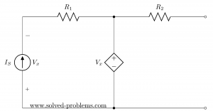
The circuit to be studied is shown in Figure 1. We would like to calculate the current through the R2 resistor and then find out all the other currents.
If we attempt to write the loop and node equations for this circuit we will have to have 5 equations, 3 loop and 2 node equations with 5 unknowns: I1, I2, I3, I4 and I5. Not very difficult to solve, but we can do better.
First, let’s redraw the schematic as in Figure 2. We eliminated R2 and will calculate the Norton equivalent current source at A-B, which is shown to the right.

With the elimination of R2 the circuit simplifies. The Norton equivalent source is well defined if we calculate the Norton current, noted here I NT , and the Norton resistor, R NT . Once I NT and R NT are known, we will reconnect R2 at the source A-B output and determine its current. This calculated current through R2 is equal with the current that flows through R2 in Figure 1, because the given circuit and the Norton source are equivalent.
What is the method to find the Norton equivalent source of this circuit?
The Norton current can be determined by applying a short circuit at the A-B output. Isc is the short circuit current and it is equal with I NT .

Now, this is still a circuit with 3 loop equations and 2 node equations. This system of equations still has 5 unknowns, in which I2 was replaced by Isc. However, this is simpler than the circuit in Figure 1, and here is why: The drop on R2 is gone. Because of that, I1 can be easily calculated from the V1, R1, V2 loop.
Next, if we find I5, then Isc, which is the Norton current I NT , can be calculated from the node equation
And here is why the calculations are simpler. We are left with 3 unknowns, I3, I4, I5 which we can find with the following 3 simple equations:

We only need I5 in this system. To solve it, first we eliminate I3 from the first 2 equations and then eliminate I4 from the resulting equation and the last one in the system. The result is I5 = 0.818 mA.
Knowing I5, the Norton current, I NT is
The next step is to determine the Norton resistance, R NT . This is the resistance seen at A-B, as in Figure 4.

Being a circuit with independent sources, the rule is to replace the voltage sources with short circuits and the current sources with open circuits. After doing that, we can see that R NT is R1 in parallel with R5, which is in series with the parallel value of R3 and R4. Therefore, R NT is
Now that we know I NT and R NT we can draw a simple circuit to find the R2 current, by applying Norton’s Theorem. The current through R2 in Figure 1 is equal with the current through R2 in Figure 5.

R2 and R NT form a current divider. Therefore, I2 is
This result shows that the Norton current source is equivalent with the Thevenin’s voltage source. If we compare this result with I2 as calculated in How to Apply Thevenin’s Theorem – Part 1 , we can see that the Norton current is
and that the Norton resistance equals the Thevenin resistance.
>>> <<<
If we need to calculate the rest of the currents in Figure 1, we can take advantage of the current we already know, I2.
I1 is easy to be found from the V1, R1, R2, V2 loop.
Then I5 = – (I1 + I2) = – 0.332 mA. From V2, R2, R5 and R3 loop, I3 is easily calculated.
And finally I4, from R3, R4, V3 loop.
Related Posts
- How to Apply Thevenin’s Theorem – Part 1, Solving Circuits with Independent Sources
- How to Apply Thevenin’s Theorem – Part 2. Nested Thevenin Sources Method
- Apply Thevenin’s Theorem to Solve a Negative Resistance Circuit, or Current Source
- Derive the Transfer Function of the Common Collector Amplifier with Thevenin’s Theorem
Leave a Comment Cancel reply
Save my name, email, and website in this browser for the next time I comment.
This site uses Akismet to reduce spam. Learn how your comment data is processed .

Electrical Concepts
Tricky but Easy Electrical Engineering!
Norton’s Theorem Explained with Example
Norton’s Theorem states that any linear bilateral circuit consisting of independent and or dependent sources viz. voltage and or current sources can be replaced by an equivalent circuit consisting of a current source in parallel with a resistance. The current source is the short circuit current across the load terminals and the resistance is the internal resistance when viewed from the open load terminals. This theorem can be applied to both AC as well as DC circuit.
Basically, Norton’s Theorem is the converse of Thevenin’s Theorem . Both the theorems tell us to about the method to a linear bilateral circuit into an equivalent circuit consisting of source and load. In both the theorems we need to find the internal resistance of circuit. The method of calculation of internal resistance is same for both the theorems.
The difference between the Norton’s and Thevenin’s theorem lies in equivalent source. It is a current source for Norton’s equivalent circuit whereas it is voltage source for Thevenin’s equivalent circuit. Another difference is the connection of internal resistance of circuit with the source. In Norton’s equivalent circuit, it is connected in parallel with the current source whereas in Thevenin’s equivalent circuit, it is connected in series with the voltage source.
Explanation of Norton’s Theorem:
To better understand the concept of Norton’s Theorem, let us consider a circuit as shown below.

For the above circuit, we will try to find the Norton’s equivalent circuit. As the very first step, we will short circuit the load resistance R L and find the short circuit current I sc . Figure below depicts this step.

Let us now find short circuit current I sc using conventional circuit analysis. The is calculated as shown below.

This current I sc is the magnitude or strength of current source of Norton’s equivalent circuit. Let us now find the internal resistance of the circuit. The main thing which should be taken care while calculating internal resistance is to replace current source by open circuit and voltage source by a short circuit. Also, keep the load terminals open and find the internal or equivalent resistance of circuit from open load terminal once you replaced all the sources. We will adopt this method.
Since, our circuit is only having a voltage source, we will replace it by a short circuit as shown below.

Let us call internal resistance R int . Therefore, R int is the series equivalent of R 1 and parallel equivalent of R 2 & R 2 .

This R int is the value of resistance which is to be connected in parallel with the current source I sc calculated earlier. Well, it’s time to draw the Norton’s equivalent Circuit.
Norton’s Equivalent Circuit:
To draw Norton’s Equivalent Circuit, we connect current source I sc in parallel with internal resistance R int . This connection is called equivalent source network. The terminals x-y of equivalent source network is then wired to load resistance R L to get the Norton’s equivalent circuit. This equivalent circuit is shown below.

While explaining Norton’s Theorem, I have already mentioned the steps to be followed to get the equivalent circuit. Further, an example is solved. This will make your concept of Norton’s Theorem as well as steps for solving problem very clear. Therefore, there is no need of separately mentioning the steps. In case you want us to elaborate the steps, kindly write in comment box.
Find the Norton’s equivalent circuit to the left of terminal x-y in the shown below.

Step-1: Short the terminals x-y as shown in figure below. Then, find the short circuit current I sc using conventional circuit analysis.

Carefully observe the above circuit. You will see that, 10 Ω and 5 Ω resistances are connected in parallel and current source of 10A is feeding this parallel combination. Short circuit current I sc is the current flowing through 5 Ω resistance. So, we can use current division rule to get this current as shown below.
I sc = (10×10) / (10+5)
= 6.67 A
This current of 6.67 is the strength of current source of the Norton’s equivalent circuit.
Step-2: Find the value of internal resistance of circuit when viewed from terminal x-y. We will replace the current source by open circuit to get the internal resistance.

Internal Resistance R int = 15 Ω
Step-3: This is the last and final step to convert a circuit into its Norton’s equivalent. In this step, we will connect 6.67 A (calculated in Step-1) current source in parallel to 15 Ω (calculated in Step-2) resistance. This gives Norton’s equivalent circuit. This is shown in figure below.

Hope you enjoyed the post. If you have any doubt / feedback, kindly write in comment box.
Leave a Comment Cancel reply
Notify me when new comments are added.
- Transf. of Sources
- Nodal Voltage
- Superposition
- Thévenin and Norton
- Electrical Measures
- + Difficult Prob.
Problem 15-3 Source: Question 2 - Test P.1 - 2012 - UFRGS.
In the circuit shown in Figure 15-03.1 :
b) Calculate the resistance of Thévenin by eliminating independent sources. Compare your result with Thévenin's resistance found in the previous item.

Solution of the Problem 15-3 - Thévenin/Norton Method
To transform sources we must decide where to start. A good start is we make an explosion of the X node. See in the Figure 15-03.2 the new configuration of the circuit.

By transforming the 9 volt source and the 20 ohm resistor which is in series with it, in a source of current in parallel with the resistor, we obtain the circuit shown in the Figure 15-03.3 . Note that the negative pole of the 9 volt source is in contact with the ground . Therefore, we must be careful in making the transformation so that we do not put the current source and the 20 ohms resistor in parallel with the 60 ohms which would completely change the circuit.

From the above circuit, we see that the two current sources provide a total current from 2.25 A to the a node. Thus, to calculate the current through the resistor of 60 ohms , just make a current divider. Note that the 10 ohms resistor must be added to 60 ohms , obtaining 70 ohms . Soon:
Therefore, we can calculate the voltage that appears in the terminals a - b for open circuit, that is, the tension of Thevenin.
Since we know the tension of Thevenin, let's calculate the short-circuit current. To do so, we have the circuit shown in Figure 15-03.4 :

Note that the 60 ohms resistor is out of the circuit due to the short between the points a - b . Therefore, the 10 ohms resistor is in parallel with that of 20 ohms . Then, the short-circuit current is the current that will cross the resistor of 10 ohms . Again, making a current divider, we have:
Now we can calculate the resistance of Thevenin, given by:
In the Figure 15-03.5 we can see the equivalent circuit of Thévenin.

To calculate Thévenin resistance, one must proceed in such a way that the voltage sources are short-circuited and the current sources are circuits. So, we have the circuit seen in the Figure 15-03.6 .

Note that with the short circuit in the voltage source, the two resistors, the 5 ohms and the 25 ohms , were shorted as well. So they're out of the loop. The resistor remained of 10 ohms in series with the resistor of 20 ohms , totaling 30 ohms . As can be seen in the circuit, this resistor is in parallel with the resistor of 60 ohms . Now, by calculating this parallel, we find R th .
Therefore, we conclude that by any method we find the same value for R th .

Solved Problems
A Source of Free Solved Problems
Find Thevenin’s and Norton’s Equivalent Circuits

The circuit has both independent and dependent sources. In these cases, we need to find open circuit voltage and short circuit current to determine Norton’s (and also Thevenin’s) equivalent circuits.
A PDF sheet of this problem with the solution and side space for notes can be downloaded below . Also, you may watch solving this problem on the video posted below. My suggestion is that you print the solution sheet and make notes on it while watching the video. Please subscribe to my YouTube channel for more videos!
Open circuit voltage

Short circuit current

Thevenin’s and Norton’s Equivalent Networks

Thevenin’s Equivalent Network

Norton’s Equivalent Network

Solution sheet
Published by yaz.
Hi! Yaz is here. I am passionate about learning and teaching. I try to explain every detail simultaneously with examples to ensure that students will remember them later too. View more posts
Join the Conversation
WHY INDEPENDENT SOURCE VALUSE COUNT TWOTIME IN KVL LAW
A good question. It is not count two times. In KVL one of them is for the dependent voltage source and second one is for the voltage drop of the current source. Let me know if you need more explanations.
Nice explanation
How do we solve nortons with 2voltage source and 1 current source present in between two of them.! For Isc only.?
What is load resistance?
what if the dependent current source depends on the thevenin’s voltage
excellent explanation
Leave a comment
Cancel reply.
Your email address will not be published. Required fields are marked *
Save my name, email, and website in this browser for the next time I comment.
Notify me of follow-up comments by email.
Notify me of new posts by email.
This site uses Akismet to reduce spam. Learn how your comment data is processed .
- Trending Now
- Foundational Courses
- Data Science
- Practice Problem
- Machine Learning
- System Design
- DevOps Tutorial
- Lami's Theorem
- Liouville’s Theorem
- Real Life Application of Rolle's Theorem
- Maximum Power Transfer Theorem
- Basic Proportionality Theorem (BPT) | Proof and Examples
- Some important mathematical proofs
- Rolle's Mean Value Theorem
- Some Basic Theorems on Trees
- Lagrange's Mean Value Theorem
- Mean Value Theorem
- Cauchy's Mean Value Theorem
- Consensus Theorem in Digital Logic
- Information Security - Return To LIBC
- C | Operators | Question 8
- C | Operators | Question 7
- C | Operators | Question 9
- C | Operators | Question 27
- C | Operators | Question 21
- C | Operators | Question 13
- Norton’s Theorem
Electrical engineering widely uses different theorems and laws to simplify the circuits involved in this field. One such theorem is known as Norton’s Theorem which is used for analysing linear circuits in electrical engineering. In this article, we will study what is Norton’s Theorem, what is the statement of this theorem, and what the circuit implementation of this theorem looks like. We will also study the step-by-step Procedure for applying Norton’s theorem to our circuit and see how it can determine IN or ISC.
Once we have successfully discussed the advantages and applications of this theorem, we will proceed to see the limitations of this theorem. Some solved examples have been solved for a better understanding of the theorem. The article concludes with some frequently asked questions that readers can refer to.
Table of Content
Circuit Diagram
- Step-by-Step Procedure
Norton’s Theorem Formula
- Disadvantages
- Applications
- Solved Example
What is Norton’s Theorem?
Norton’s theorem is a popular theorem used for simplifying linear circuits that use multiple independent and dependent sources. It is used to replace circuit elements by Norton’s current source which is in parallel with Norton’s resistance. Basic circuit equations are then written to find the current in different elements of the circuit. It is important to note that the theorem does not apply to non-linear circuits since these circuits don’t follow Ohm’s law .
Norton’s Theorem Statement
Let us look at the official statement of Norton’s Theorem
Norton’s theorem states that any linear circuit can be simplified to an equivalent circuit consisting of a single current source and parallel resistance that is connected to a load.
Now we will study the meaning of this statement through some circuit diagrams.
Norton’s Theorem Circuit Diagram
Here is the circuit diagram for Norton’s Theorem

Norton’s theorem circuit
I norton : Norton’s current source R norton : Norton’s resistance
This circuit is a general simplification of a complex circuit which is done using Norton’s Theorem. If you carefully observe, the circuit has been reduced to have one current source and one resistance known as Norton’s current source and Norton’s resistance. This new circuit is used for calculating the voltage and current developed across the load resistance. Note that the equivalent circuit will depend on the type of load and the circuit elements. The basic circuit has been made by short circuiting the voltage sources and open circuiting all the independent current elements which are then replaced by Norton’s equivalent of these values. The steps for determining the current and voltage after the equivalent circuit is made have been explained below.
Norton’s Theorem Step-by-Step Procedure
Here are the steps to be followed for applying Norton’s Theorem

Steps for Norton’s Theorem
Step 1: Observe all the voltage sources and short them resulting in plain wires. After that observe all the current sources and open-circuit them which will give you all the internal resistances of the circuit.
Step 2: We consider a network shown above to apply Norton’s theorem. We will short circuit all the voltages. The circuit after short circuit has been given and we can calculate current I N across the terminals AB
Calculating I N: The whole circuit is replaced by an equivalent resistance R L to replace the short circuit . Now since we replaced the shorted element with Norton’s equivalent, the short circuit current I SC will be equal to the Norton current I N . The formula for calculating the Norton’s current has been explained in the later section.
Calculating I SC : The final circuit network is displayed in the figure and the left side of terminal AB is replaced by Thevenin’s equivalent resistance R TH . Let us see the formula that will be used for calculating the values of I sc , I N and thevenin voltage. The formula for the Norton’s current or short circuit current will be given by
I sc = I N = V th / R th
The derivation will be shown in the later parts.
From our previous derivations, we can write down the formula as
V Th = R 2 /(R 1 +R 2 ). V and R Th = R 3 + (R 1 .R 2 )/(R 1 +R 2 )
Now, we can calculate the short circuit current as
I SC = V Th / R Th
When Norton’s theorem is applied to any general circuit, the current source is in parallel with resistance and we can write the current across the load as
I L = I N . R N /(R N +R L )
Advantages of Norton’s Theorem
Let us see some advantages of Norton’s Theorem
- Norton’s theorem simplifies the overall complexity of the circuit and makes circuit solving an easy process.
- Norton’s theorem reduces the size of the circuit by replacing the different current sources with Norton’s resistance and Norton’s voltage.
- Norton’s theorem can be used to find current and voltage across a single element in the network without caring about other elements in a linear circuit.
- Norton’s Theorem can be useful for studying the nature of circuits and understanding how internal resistance is dependent on other resistances.
- Norton’s Theorem along with Thevenin’s theorem is used by engineers to solve complex circuits.
Limitations of Norton’s Theorem
Let us see some limitations of Norton’s Theorem
- Norton’s theorem can only be applied to linear circuit elements and it fails for non linear circuits.
- Circuits that deal with magnetic fields can affect the resistance of the overall circuit so Norton’s theorem can’t be applied to such magnetic circuits .
- Using Norton’s Theorem for the analysis of complex circuits can be a difficult task due to the enumerable mathematical calculations.
- Norton’s Theorem is based on certain assumptions which make the results of Norton’s Theorem inaccurate in real world due to introduction of real world parameters.
- Norton’s Theorem focuses on current carrying elements therefore we have to use Thevenin Theorem to study the voltage distribution.
Applications of Norton’s Theorem
Let us see some Applications of Norton’s Theorem
- The ease of application of Norton’s Theorem makes it a suitable concept to be taught to high school students so it is used for educational purposes.
- Telecommunication engineering employs the use of Norton’s Theorem to study network models and optimize the process of communication.
- Norton’s Theorem can be used for load matching where Norton’s Theorem is used to calculate the value of load to minimize power loss.
- Norton’s Theorem is commonly used by engineers for circuit analysis by replacing the complex circuit with simpler components.
- Norton’s Theorem can also be used for finding faults in circuits by simplifying the circuit at every step and identifying the potential cause of error.
Norton’s Theorem Solved Example
Q.Solve the value of current and voltage across the load branch in the given circuit using Norton’s Theorem.

We will calculate Norton’s resistance by shorting the load resistance branch. The circuit will now look like this

The total resistance for the given circuit is
R eq = 2 + 3×6/(3+6) ∴ R eq = 4 ohm ∴ R T = 4 ohm
We will calculate current using ohm’s law
I Th = V/R Th ∴ I th = 12/4 = 3A
Using current divider rule, we will calculate the current across the load element
I sc = I N ∴ I sc = 3×6/(3+6) ∴ I sc = 2A
Now we will calculate the Norton’s resistance by open circuiting the current sources. The 12 V voltage will become 0 and be replaced by a short. Here is the circuit

The equivalent voltage will be given by
R eq = 3 + 6×2/(2+6) ∴ R eq = 3 + 1.5 ∴ R eq = 4.5 ohm
We will calculate thevenin voltage by applying Norton’s resistance across the current source. Therefore, using ohms law
I L = I n x [R n ÷ (R n + R L )] ∴ I L = 2A x (4.5Ω /( 4.5Ω + 1.5Ω)) ∴ I L = 1.5A
We can give voltage across load resistance by
V L = I L x R L ∴ V L = 1.5A x 1.5Ω ∴ V L = 2.25V
Q.Solve the value of current across the load branch in the given circuit using Norton’s Theorem.

Circuit diagram
We will calculate Norton’s resistance by shorting the load resistance branch. The circuit will now look like this after removing 5 ohm resistance.

Let us calculate the equivalent resistance of the circuit using series and parallel method.
R = (5+5)Ω+(10Ω||(4+6)Ω) ∴ R =10+10×10/(10+10) ∴ R =10+5=15Ω
The total current can be calculated from ohm’s law
I=V/R ∴ I=30/15=2A
The Norton’s current can be calculated by current divider rule
I sc = I N = I×10/(10+4+6) ∴ I N = 2×(10/20)=1A
Now we need to calculate Norton’s resistance so we short circuit the voltage source, the circuit will look like

Norton’s resistance
R 1 =10Ω||10Ω ∴ R 1 =10×10/(10+10)=5Ω ∴ R n =R AB =4+R 1 +6 ∴ R 1 = 4+5+6 = 15Ω
Now we will make Norton’s equivalent circuit by adding Norton’s equivalents in the circuit.
R L =5Ω ∴ I L =I N .R N /(R N +R L ) ∴ I L =1×15/(15+5) ∴ I L = 15/20=0.75
We have seen how we can use Norton’s Theorem to simplify the linear circuits and find the current distribution in the circuit. The derivation of Norton’s voltage and resistance has been explained and some solved examples have been provided to build better concepts. We have seen how Norton’s Theorem is a useful tool that finds its application in fields like circuit analysis. Despite the advantages offered by Norton’s Theorem, there are some limitations associated with it which have been discussed briefly. Frequently asked questions have been provided below.
Norton’s Theorem – FAQs
What are linear circuits.
Linear circuits are the circuits that obey superposition principle making the output proportional to the input fed to the circuit.
Why can’t we use Norton’s Theorem in non linear circuits?
The reason why we can’t use Norton’s Theorem in non linear circuits is that non linear circuit elements don’t follow superposition principle and KCL and KVL used in Norton’s theorem become inapplicable.
How is Norton’s Theorem related to Thevenin’s theorem?
Thevenin’s Theorem deals with a voltage source and Norton’s Theorem uses a current source. The Thevenin voltage is calculated by multiplying Norton’s resistance and Norton’s current.
Please Login to comment...
Similar reads.
- Electronics
- Electric circuits
- Electronics Engineering
Improve your Coding Skills with Practice
What kind of Experience do you want to share?

- Google Login
- All Activity
- Ask a Question
Thevenin's Theorem Solved Example 1 : with dependent source
- thevenin-theorem
- dependent-source
Please log in or register to add a comment.
Solution : Thevenin's Theorem Solved Example 1 : with dependent source
Please log in or register to answer this question.
Related questions.
Thevenin's Theorem with Dependent Source Solved Example Answer : Solution : Thevenin's Theorem with Dependent Source Solved Example ...

Thevenin's Theorem Solved Example 3 : with dependent source Answer : Solution :Thevenin's Theorem Solved Example 3 : with dependent source ...

Thevenin's Theorem Solved Example 2 : with dependent source Answer : Solution : Thevenin's Theorem Solved Example 2 : with dependent source ...

Nodal Analysis with Dependent Source Solved Example 2 Answer : Solution : Nodal Analysis with Dependent Source Solved Example 2 ...
- nodal-analysis

Steps to solve thevenin's theorem problem Answer : To solve a problem using Thevenin's theorem, follow these steps: Step 1: Understand the problem Read the problem statement carefully and identify the circuit or network for which you need ... may vary depending on the complexity of the circuit and the available tools for circuit analysis....

Nodal Analysis with Supernode and Dependent Source | Supernode with Dependent Source Answer : Solution : Nodal Analysis with Supernode and Dependent Source | Supernode with Dependent Source ...

Mesh Analysis with dependent source | mesh analysis electrical engineering Answer : Solution : Mesh Analysis with dependent source | mesh analysis electrical engineering ...
- mesh-analysis

Nodal Analysis Solved Example 1 Answer : Solution : Nodal Analysis Solved Example 1 ...

How is Thevenin's theorem used to simplify complex circuits into a voltage source and series resistance? Answer : Thevenin's theorem is a fundamental principle in electrical engineering that simplifies complex circuits containing multiple resistors, voltage sources, and current sources into a simpler ... for simplified calculations and straightforward analysis of circuit behavior under various load conditions....
- basic circuit concepts

Network Theorems And Circuit Theory - Thevenin's Theorem with sinusoidal excitations Answer : Thevenin's Theorem is a fundamental concept in circuit theory that helps simplify complex linear electrical circuits, particularly those with sinusoidal excitations (AC circuits). The theorem ... work with phasor diagrams and complex impedance calculations to analyze AC circuit behavior accurately....
- network theorems and circuit theory

Network Theorems And Circuit Theory - Thevenin's Theorem with d.c Answer : Thevenin's Theorem is a fundamental concept in circuit theory that simplifies complex linear circuits into simpler equivalents. It helps analyze and solve electrical circuits more efficiently by reducing ... to simplify analysis but doesn't provide deeper insights into the circuit's workings....

How can you analyze circuits using the Norton's theorem for circuits with multiple dependent sources? Answer : To analyze circuits with multiple dependent sources using Norton's theorem, you need to follow these general steps: Understand Norton's Theorem: Norton's theorem states that any linear ... results and consider the direction of currents and voltages according to your chosen reference directions....
- circuit analysis

How can you analyze circuits using the superposition theorem for circuits with multiple dependent sources? Answer : Analyzing circuits with multiple dependent sources using the superposition theorem can be a bit more complex than circuits with only independent sources. However, the process follows the same ... each independent source, and then combining the results to determine the overall circuit response....

How can you analyze circuits using the Norton's theorem for circuits with dependent sources? Answer : Analyzing circuits using Norton's theorem can be a powerful tool, even in circuits with dependent sources. Norton's theorem states that any linear circuit with multiple sources and resistors can ... verify your results by comparing the original circuit's behavior with the Norton equivalent circuit....

How do you analyze circuits with dependent sources using the superposition theorem? Answer : To analyze circuits with dependent sources using the superposition theorem, you can follow these steps: Understand the Circuit: Make sure you have a clear understanding of the circuit's components, ... in the circuit. If the circuit contains nonlinear elements, this method may not be applicable....

How do you analyze circuits using the source transformation method for networks with dependent sources? Answer : Analyzing circuits using the source transformation method can be a powerful technique, even when the circuit contains dependent sources. The source transformation method involves converting a voltage source in ... -check your work and verify the final results with other analysis methods if possible....

How do you analyze circuits with dependent sources using the method of source transformations? Answer : Analyzing circuits with dependent sources using the method of source transformations is a powerful technique to simplify and solve complex circuits. The method of source transformations involves ... sources and simplify complex circuit configurations, making them easier to understand and solve....

Network Theorems And Circuit Theory - Thevenin's Theorem Answer : Thevenin's Theorem is a fundamental concept in electrical circuit theory, specifically in the analysis of linear electrical networks. It provides a method to simplify complex circuits by representing ... understand, and it's widely used in various applications of circuit theory and electronics....

Explain the concept of Thevenin's theorem in circuit analysis. Answer : Thevenin's Theorem is a fundamental concept in electrical circuit analysis that simplifies complex networks of components, such as resistors, voltage sources, and current sources, into an ... theorem is widely used in electrical engineering for circuit design, analysis, and troubleshooting....
- electronics

Explain Thevenin's theorem and its applications. Answer : Thevenin's theorem is a fundamental concept in electrical engineering and circuit analysis. It simplifies complex electrical circuits by representing them as a single voltage source and a ... analysis, and it greatly simplifies the process of understanding and designing complex electrical circuits....

How can Thevenin's theorem and Norton's theorem simplify complex circuits? Answer : Thevenin's theorem and Norton's theorem are powerful circuit analysis techniques that can simplify complex circuits and make them easier to understand and solve. Both the theorems are used ... , analyze, and solve complex circuits, especially when dealing with multiple resistors and sources....
What is Thevenin's theorem? Answer : Thevenin's theorem is a fundamental concept in electrical engineering and circuit analysis. It provides a method for simplifying complex electrical circuits, reducing them to simpler equivalent ... with a single voltage source and resistor combination, making calculations much more straightforward....

How is maximum power transfer achieved using Thevenin's or Norton's theorem? Answer : Maximum power transfer can be achieved using either Thevenin's or Norton's theorem when the load resistance matches the equivalent Thevenin or Norton resistance of the circuit. Let's take a ... transfer is often optimized based on the specific requirements and constraints of the circuit or system....

Describe the principle of Thevenin's theorem and its usefulness. Answer : Thevenin's theorem is a fundamental concept in electrical engineering that simplifies complex electrical networks, making analysis and design more manageable. It states that any linear two- ... analysis, enabling engineers to understand, design, and troubleshoot electrical systems more effectively....

Discuss the Norton theorem and its relation to Thevenin's theorem. Answer : Norton's theorem and Thevenin's theorem are two fundamental principles in electrical circuit analysis that facilitate the simplification of complex circuits to simpler equivalents. Both theorems ... them effectively and interchangeably based on the situation and requirements of their analysis....

State Thevenin's theorem. Answer : Thevenin's theorem is a fundamental principle in electrical circuit analysis. It states that any linear electrical network containing voltage sources, current sources, and resistances can be replaced with an ... of interest, and the internal details of the network are not necessary for the analysis....

Define Thevenin's theorem. Answer : Thevenin's theorem is a fundamental principle in electrical circuit analysis that simplifies complex linear circuits containing multiple resistors, voltage sources, and current sources into a more manageable ... and design, making it a valuable tool for electrical engineers and circuit designers....

How do you analyze circuits using the supernode method for networks with dependent sources? Answer : The supernode method is a powerful technique for analyzing circuits that involve dependent sources. It's an extension of the standard nodal analysis and is particularly useful when dealing with ... KCL, considering the currents associated with both independent and dependent sources in the circuit....

How can you analyze circuits using the mesh-current method for circuits with dependent sources? Answer : Analyzing circuits using the mesh-current method is a powerful technique to solve for unknown currents in a circuit. This method is especially useful when dealing with circuits containing dependent ... nonlinear elements, an iterative approach may be necessary to converge on the correct solution....
How can you analyze circuits with dependent sources using the method of controlled sources? Answer : The method of controlled sources is a powerful technique used to analyze circuits with dependent sources. It involves replacing the dependent source with an equivalent controlled source and then ... circuit analysis methods will help you choose the most suitable approach for a given problem....

How can you use nodal analysis to analyze circuits with voltage sources and dependent sources? Answer : Nodal analysis is a powerful method used to analyze electrical circuits. It involves writing Kirchhoff's current law (KCL) equations for each node in the circuit to determine the node ... circuits. In such cases, circuit simulation software can be helpful for efficient analysis and verification....

How do you analyze circuits with dependent voltage sources? Answer : Analyzing circuits with dependent voltage sources involves using the principles of circuit analysis while considering the dependency of the voltage sources on other circuit variables. Dependent voltage ... can be valuable for analyzing circuits with dependent sources in real-world applications....

How do you analyze circuits with dependent sources? Answer : Analyzing circuits with dependent sources requires a systematic approach to solve for the desired variables (usually voltages and currents) using the equations that govern the circuit. Dependent ... simulation tools like SPICE can be valuable for verifying results in more complicated scenarios....

How does a Light Dependent Resistor (LDR) vary its resistance with light intensity? Answer : A Light Dependent Resistor (LDR), also known as a photoresistor, is a type of semiconductor device that exhibits a change in resistance with varying light intensity. Its resistance decreases ... various applications, such as light sensors, automatic street lights, and exposure control in cameras....

How do you analyze circuits with dependent and independent sources using network theorems? Answer : Analyzing circuits with both dependent and independent sources can be challenging, but network theorems provide useful tools to simplify and solve such circuits. Here's a step-by-step guide to ... a better understanding of their behavior and find the most suitable network theorem for each case....

How do you analyze circuits with dependent and independent sources using network theorems? Answer : Analyzing circuits with both dependent and independent sources using network theorems involves applying the fundamental principles of circuit analysis while considering the effects of these sources. ... understanding of the underlying principles of circuit theory to apply these theorems effectively....

How do you analyze circuits with dependent and independent sources using network theorems? Answer : Analyzing circuits with dependent and independent sources using network theorems follows similar principles to analyzing circuits with only independent sources. The main network theorems used for ... use other techniques to express the dependent source values before applying network theorems....
How do you analyze circuits with dependent and independent sources using network theorems? Answer : Analyzing circuits with dependent and independent sources using network theorems follows a similar process to analyzing circuits with only independent sources. The key difference is that you need to consider ... use of multiple theorems or a combination of techniques to arrive at the final solution....

How do you analyze circuits with dependent and independent voltage/current sources? Answer : Analyzing circuits with dependent and independent voltage/current sources involves applying basic circuit analysis techniques, such as Kirchhoff's voltage and current laws, Ohm's law, and other network ... techniques, such as nodal analysis or mesh analysis, to solve the system of equations....

What are the different methods of solving circuits with dependent sources? Answer : When dealing with circuits that contain dependent sources (sources whose values depend on other circuit variables, such as voltage or current), the analysis can become more complex than ... and characteristics of dependent sources is crucial to effectively solving circuits that involve them....

Network Theorems And Circuit Theory - Tellegen's Theorem with d.c Answer : Tellegen's theorem is a fundamental principle in electrical circuit theory that relates the power flows within a network or circuit. It states that for any linear, bilateral electrical network, the ... a direct solving method but rather as a way to validate the results of circuit analysis....

Network Theorems And Circuit Theory - Tellegen's Theorem with sinusoidal excitation Answer : Tellegen's theorem is a fundamental principle in electrical circuit theory that relates the power consumed or supplied by circuit elements to the network topology. It provides a way to ... 's often used in conjunction with other circuit analysis techniques to solve complex electrical networks....
Network Theorems And Circuit Theory - Superposition Theorem with sinusoidal excitation Answer : The Superposition Theorem is a fundamental concept in circuit theory that allows you to analyze linear circuits with multiple independent sources. It states that the response (voltage or current) in ... the same principles apply, but you'll work with phasor representations of voltages and currents....

Network Theorems And Circuit Theory - Superposition Theorem with d.c Answer : The Superposition Theorem is a fundamental concept in electrical circuit theory that simplifies the analysis of linear circuits with multiple sources. It states that the response (voltage or current) ... is primarily used for analysis purposes and not for solving real-world circuit design problems....

Network Theorems And Circuit Theory - Reciprocity Theorem with sinusoidal excitation Answer : The Reciprocity Theorem is an important concept in network theory and circuit analysis. It states that the ratio of the response in one circuit due to the excitation in another circuit is ... fulfill its assumptions, and be cautious with signs and reference directions to ensure accurate results....

Network Theorems And Circuit Theory - Reciprocity Theorem with d.c Answer : The Reciprocity Theorem is a fundamental concept in circuit theory that applies to linear, time-invariant electrical networks. It states that the ratio of a response (such as voltage ... measuring impedance parameters, and understanding the behavior of sensors or transducers in reciprocal networks....

Network Theorems And Circuit Theory - Norton's Theorem with sinusoidal excitation Answer : Norton's Theorem is a fundamental concept in circuit theory that simplifies the analysis of linear electrical networks. It is a counterpart to Thevenin's Theorem and helps in finding equivalent ... 'll use phasor analysis to determine the Norton current source and the Norton equivalent resistance....

Network Theorems And Circuit Theory - Norton's Theorem with d.c Answer : Norton's Theorem is a fundamental concept in circuit theory that provides a way to simplify linear electronic circuits containing multiple voltage or current sources. It's named after Edward ... with a resistor. This theorem is extremely useful for circuit analysis, design, and troubleshooting....

Network Theorems And Circuit Theory - Millman's Theorem with sinusoidal excitation Answer : Millman's theorem is a network theorem used in circuit theory to simplify the analysis of complex electrical circuits. It's analogous to the more commonly known voltage and ... It helps engineers and researchers quickly determine node voltages without going through complex algebraic manipulations....

Network Theorems And Circuit Theory - Millman's Theorem with d.c Answer : Millman's theorem is a network theorem in circuit theory that allows you to simplify complex parallel resistor-voltage source networks into a single equivalent voltage source and a single equivalent ... alternating current (a.c.) circuits due to the consideration of impedance and phase differences....

- All categories
- Basic Electricity / Concepts (123)
- Alternators (28)
- D.C. Generators (31)
- D.C. Motors (63)
- Electric Heating (10)
- Electric Traction (3)
- Electric Welding (7)
- Electrical Engineering Materials (37)
- Electrostatics (72)
- Electrolysis and Storage of Batteries (60)
- Electromagnetic Induction (40)
- Illumination (21)
- Industrial Drives (9)
- Magnetic Circuit and Electromagnetism (126)
- Network Theorems And Circuit Theory (37)
- Poly-phase(3) Induction Motors (51)
- Polyphase Circuits (56)
- Resistance and Ohms law (14)
- Rectifiers and Converters (24)
- Single Phase Induction Motors (54)
- Switchgear and Protection (24)
- Synchronous Motors (32)
- Transformers (71)
- Electrical Power (Transmission, Distribution & Generation) (87)
- A.C. Fundamentals (241)
- Measurement and Instrumentation (216)
- Control Systems (50)
- Electrical Engineering (9.5k)
- Electronics Engineering (4.5k)
- Electrical Circuits (2)
- Electrical and Electronic Measurements (0)
- Circuit Analysis (2.5k)
- Basic Circuit Concepts (1.1k)
- Kirchhoff's laws (current and voltage laws) (0)
- Node analysis (3)
- Mesh analysis (1)
- Superposition theorem (2)
- Thevenin theorems (5)
- Norton theorems (0)
- Maximum power transfer theorem (0)
- DC Circuit Analysis (0)
- AC Circuit Analysis (9)
- Network Theorems (0)
- Three-Phase Circuits (950)
- Transient Analysis (150)
- Frequency Response Analysis (0)
- Two-Port Networks (158)
- Power Electronics (1.1k)
- AC Power Analysis (2)
25.7k questions
25.9k answers
IMAGES
VIDEO
COMMENTS
Worked Problems: Thevenin and Norton Equivalents as Problem 4.2. In this problem we have both dependent and independent sources. In the solution shown, we find the open circuit voltage and the short circuit current, and from that we calculate the Thevenin resistance. We then find the Thevenin resistance using a test voltage source, and finally ...
In this video, Norton's Theorem is explained with the Solved Examples.The timestamps for the different topics covered in the video :0:00 Introduction0:20 Nor...
Solved Problem 1. For the given circuit, determine the current flowing through 10 Ω resistor using Norton's theorem. Since the question here, is to determine the current through 10 Ω resistor, it is considered as the load. (a) To find Norton's current, Remove the load resistor (10 Ω), short it with a wire and the circuit is redrawn as below.
Norton's Theorem. Easy Step by Step Procedure with Example (Pictorial Views) This is another useful theorem to analyze electric circuits like Thevenin's Theorem, which reduces linear, active circuits and complex networks into a simple equivalent circuit. The main difference between Thevenin's theorem and Norton's theorem is that, Thevenin's theorem provides an equivalent voltage source and ...
Norton's Theorem Solved Problem with Dependent Sources. We will find I sc and R N for the circuit shown in the following figure. In order to determine the short-circuit current, we'll short-circuit terminals a and b as shown in the following figure and V 2 = 0. Apply KCL to node 1:
gmail Id: [email protected] Don't Forget to subscribe our Channel Lectures Content: In this Lecture I explained a Norton's Theorem and ...
Formally, Norton's theorem states: \[\text{Any single port linear network can be reduced to a simple voltage source, } I_n, \text{ in parallel with an internal impedance } Z_n. \nonumber \] The process of finding a Norton equivalent is very similar to finding a Thévenin equivalent. First, the Norton impedance is the same as the Thévenin ...
This article explains the step-by-step process for determining the Norton equivalent circuit and Norton's theorem.Norton's theorem is similar to Thevenin's theorem in that it also allows us to simplify any linear circuit to an equivalent circuit. However, instead of using a voltage source and a series resistance, the Norton equivalent circuit consists of a current source with a parallel ...
Norton's Theorem is a powerful tool for solving electrical circuits. Like Thevenin's Theorem, it simplifies the circuit one needs to study and dramatically reduces potential calculation errors.. Norton's Theorem states that networks with voltage and current sources, as well as resistors are electrically equivalent to one single current source and one single resistor in parallel with the ...
Norton's Theorem (also known as the Mayer-Norton theorem) states that it is possible to simplify any linear circuit to an equivalent circuit with a single current source and equivalent parallel resistance connected to a load. The simplified circuit is known as the Norton Equivalent Circuit. More formally, Norton's theorem can be stated as ...
Network Theory: Solved Question on Norton's TheoremTopics discussed:1) Calculating Norton's current when the network has a dependent source.2) Calculating No...
Norton's Theorem Solved Examples. Example 1: In the network shown in figure, calculate the current through the load resistor RL R L by using Norton's Theorem. Fig : Circuit diagram. Solution 1: Finding ISC I S C or IN I N. Step 1 : Remove the load resistance RL = 5Ω R L = 5 Ω and short circuit the terminals A and B.
substitution step, and it will make a mess of your problem. Better to avoid. Thevenin/Norton with a dependent source As mentioned above, Thevenin and Norton's theorems only apply to circuits containing linear dependent sources. The test-source method of Thevenin's theorem will always work with dependent sources, and needs no further discussion.
Edward Lawry Norton. In direct-current circuit theory, Norton's theorem, also called the Mayer-Norton theorem, is a simplification that can be applied to networks made of linear time-invariant resistances, voltage sources, and current sources. At a pair of terminals of the network, it can be replaced by a current source and a single resistor ...
Norton's Theorem states that any linear bilateral circuit consisting of independent and or dependent sources viz. voltage and or current sources can be replaced by an equivalent circuit consisting of a current source in parallel with a resistance. The current source is the short circuit current across the load terminals and the resistance is the internal resistance when viewed from the open ...
Find Vo using Thevenin's theorem. Problems - In class. Find Io using Thevenin's or Norton's theorem. Problems - In class. Problems - In class. Problem 5: Find the Thevenin equivalent circuit for the following circuit with respect to the terminals AB (Irwin - Example 5.8) Problems - In class. Problem 6: Find the Thevenin ...
Figure 15-03.1. Solution of the Problem 15-3 - Thévenin/Norton Method. Item a. To transform sources we must decide where to start. A good start is we make an explosion of the X node. See in the Figure 15-03.2 the new configuration of the circuit. Figure 15-03.2. By transforming the 9 volt source and the 20 ohm resistor which is in series with ...
The figure above illustrates a circuit with VCVS and its Norton equivalent model as seen from Port B. Given that Vo=5V,A=2,R1=1Ω,R2=3Ω,R3=5Ω, determine the Norton current IN and Norton resistance RN. Attempts: I calculated Vout=7.857 V; u=5.714 V. I don't know how to calculate the Norton resistance, since the dependent source 2u cannot be ...
Solution. The circuit has both independent and dependent sources. In these cases, we need to find open circuit voltage and short circuit current to determine Norton's (and also Thevenin's) equivalent circuits. A PDF sheet of this problem with the solution and side space for notes can be downloaded below. Also, you may watch solving this ...
Thevenin's theorem can be applied when analyzing a circuit with dependent sources. In this case, all independent sources are turned off and the R Th is calculated by applying a current source or voltage source at the open terminal. When using a voltage source, it can be assumed to be 1V for simple calculations.
Norton's theorem is a popular theorem used for simplifying linear circuits that use multiple independent and dependent sources. It is used to replace circuit elements by Norton's current source which is in parallel with Norton's resistance. Basic circuit equations are then written to find the current in different elements of the circuit.
Steps to solve thevenin's theorem problem. Answer : To solve a problem using Thevenin's theorem, follow these steps: Step 1: Understand the problem Read the problem statement carefully and identify the circuit or network for which you need ... may vary depending on the complexity of the circuit and the available tools for circuit analysis ...